
Article Contents
ATS (Automatic Transfer Switch): The Complete Guide


Key takeaways
An ATS (automatic transfer switch) is a device that, with no human involvement, moves the load from the main power source to the backup source within seconds of the voltage disappearing. The transfer time of modern devices ranges from 50 ms in electronic models to 1-2 seconds in motorised cabinets.
Key point: an ATS only switches sources — it does not stabilise the voltage, it does not protect against earth leakage and it does not start the generator engine by itself. Its rating is chosen no lower than that of the main breaker, with a 20-30% margin, while the number of poles (2P, 3P or 4P) is determined by the earthing arrangement and the type of backup source.
Hello! This material was prepared by the UEC engineering department. We design and manufacture our own SB-ATS series of automatic transfer switches, and every day we equip backup supply inputs for private houses, boiler rooms, pumping stations and commercial facilities across Ukraine.
This guide brings together our engineering experience: from the operating principle to concrete selection tables by current and pole configuration, taking into account the requirements of the Ukrainian Electrical Installation Code (PUE) and the international standard IEC 60947-6-1.

⚠ WARNING! Working with electrical equipment is life-threatening!
Connecting an ATS and a backup power supply (especially a generator input) involves the risk of backfeed and requires a qualification of at least electrical safety group III. Have the installation carried out by a licensed electrician.
What an ATS is and why you need one
An ATS is a system that automatically transfers the load from the main power source to the backup source (and back) when the main source fails; in essence, it is an automatic backup power transfer switch. In plain terms: when the grid voltage disappears, the ATS brings the backup online by itself — a second incoming supply, a generator or an inverter — and when the grid is restored, it returns the load to it.
The Ukrainian abbreviation AVR stands for automatic transfer of the backup supply. The international synonym is ATS (automatic transfer switch), and in standards terminology such devices belong to the class of transfer switching equipment (TSE) under IEC 60947-6-1 [1].
What an ATS is needed for in practice:
- Uninterrupted supply for critical loads. A gas boiler, a heating circulation pump, a borehole pump, a refrigerator, a server or an alarm system must not be left without power.
- Automation instead of manual work. Without an ATS, after every outage someone has to physically throw the isolator and start the generator. The ATS does this by itself.
- Protection against human error. A properly designed ATS makes it impossible to connect the grid and the generator at the same time — the most dangerous mistake in backup power supply.
What an ATS does NOT do:
it does not stabilise the voltage, it does not protect against earth leakage (that is the job of an RCD) and it does not start the generator engine without a separate auto-start unit. An ATS only switches which source the load is connected to.
How an ATS works: three operating modes
The operation of an ATS is based on continuous monitoring of the main source parameters (presence of voltage, frequency, phase symmetry) and automatic transfer to the backup source when those parameters move outside the permitted limits. The logic is handled by a controller, while the transfer itself is performed by the power section — contactors, a motorised mechanism or a reversing isolator.
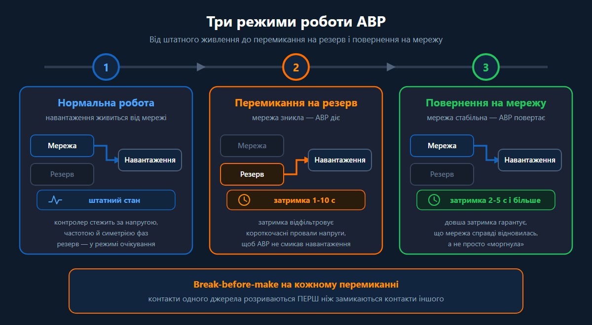
Mode 1: normal operation from the grid
In normal operation the load is supplied from the main source (the grid). The controller constantly "listens" to the incoming supply: it monitors the presence of all three phases, the voltage level and the frequency. The backup source is de-energised at that point or runs at idle (the generator in standby). This is the baseline state in which the device spends most of its time.
Mode 2: transfer to the backup source
As soon as the grid disappears or its parameters move outside the limits, the controller holds a transfer delay — in practice 1-10 seconds (in many controllers adjustable within a range of 0-240 s) [5]. This delay is not a defect but a safeguard: it filters out short voltage dips ("flicker") so that the ATS does not jerk the load on every brief disturbance. If the grid stays absent for longer than the delay, the device opens the circuit of the main source and closes the circuit of the backup source.
Mode 3: return to the grid
When the main supply is restored and holds steady throughout the return delay (2-5 seconds and longer) [5], the ATS transfers the load back to the grid and puts the backup source into standby. The return delay is longer for technological reasons: it guarantees that the grid has not merely "blinked" but has genuinely recovered.
The key safety principle — break-before-make:
the contacts of one source open BEFORE the contacts of the other close. Connecting the grid and the generator simultaneously, with unsynchronised voltage, phase and frequency, causes a short circuit and destroys equipment [3]. That is exactly why a quality ATS physically has no position in which both sources are connected.
What types of ATS exist
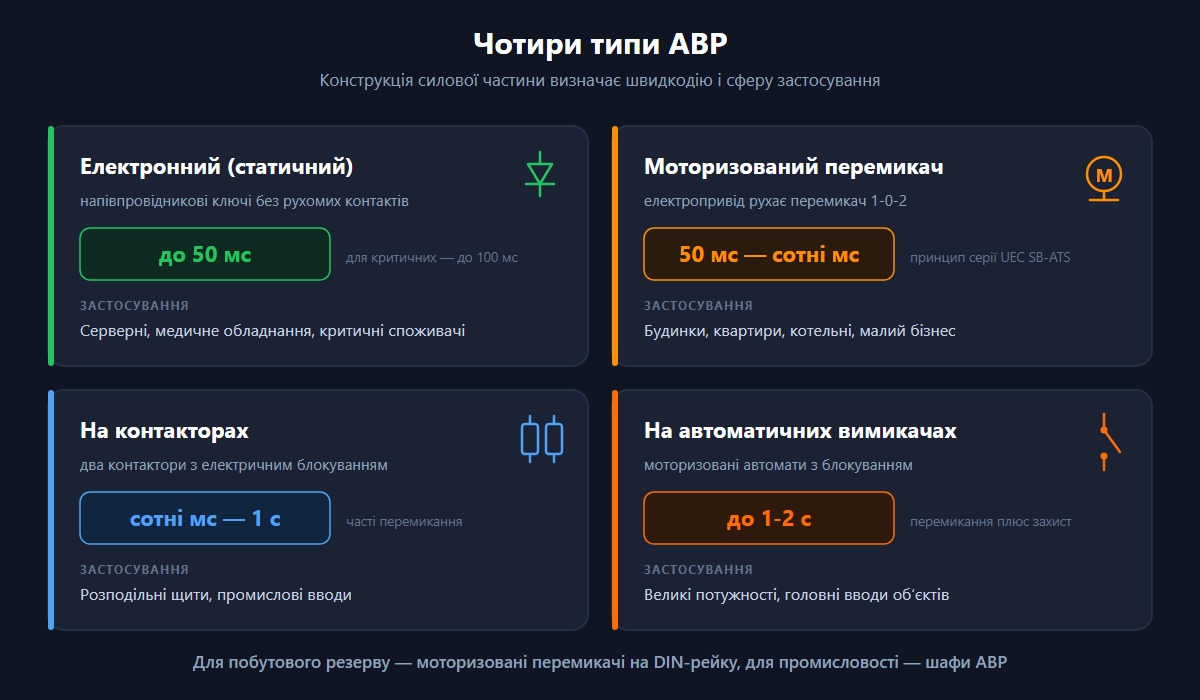
By the design of their power section, ATS units fall into four main types that differ in switching speed, service life and field of application. For domestic backup power the usual choice is a compact motorised changeover switch on a DIN rail; industry uses cabinets built on contactors or on motorised circuit breakers.
| ATS type | How it switches | Typical transfer time | Typical application |
|---|---|---|---|
| Electronic (static) | Semiconductor switches with no moving contacts | up to 50 ms (up to 100 ms for critical loads) | Server rooms, medical equipment, critical loads |
| Motorised changeover switch | An electric drive moves a 1-0-2 changeover switch | 50 ms to hundreds of ms | Houses, apartments, boiler rooms, small business |
| Contactor-based | Two contactors with electrical interlocking | hundreds of ms to 1 s | Distribution boards, industrial incoming supplies |
| Breaker-based | Motorised breakers with interlocking | up to 1-2 s | High power, main incoming supplies of facilities |
The transfer-time benchmarks are given from industry data: electronic/static ATS units — up to 50 ms (for critical loads no more than 100 ms is quoted), motorised devices — from hundreds of milliseconds to 1-2 seconds in real cabinets, taking the mechanics and the controller delays into account [4].
How a contactor-based ATS differs from a breaker-based one
A contactor-based ATS is simpler and cheaper and switches faster, but the contactor keeps its coil energised permanently and has a limited mechanical service life — it is optimal for frequent transfers and moderate currents. A breaker-based ATS is more expensive and switches more slowly, yet it combines the transfer function with short-circuit protection and is rated for the high currents of main incoming supplies.
What a motorised changeover switch is (the SB-ATS series as an example)
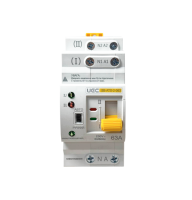
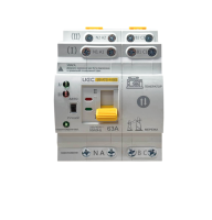
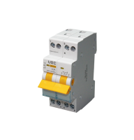
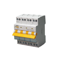
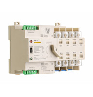
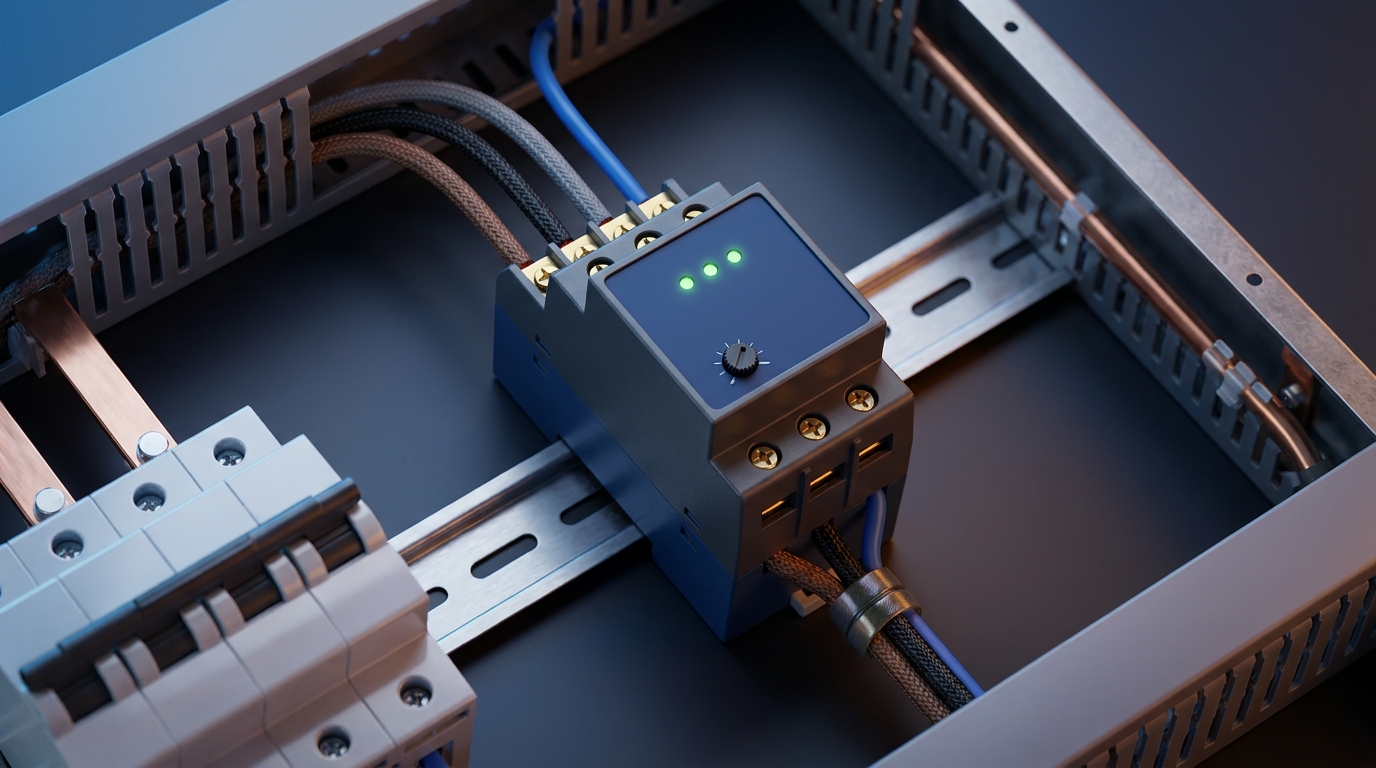
A motorised changeover switch is a three-position switch (positions 1-0-2: main source, neutral, backup; covered in more detail in the article on the changeover switch and 1-0-2 isolator) with an electric drive and manual backup operation. The UEC SB-ATS series is built on exactly this principle: the device transfers the load to the backup source automatically, and can be switched by hand when required. Transfer time in automatic mode is 50 ms, DIN-rail mounting, IP30 degree of protection.
How an ATS differs from a manual changeover switch and a voltage relay
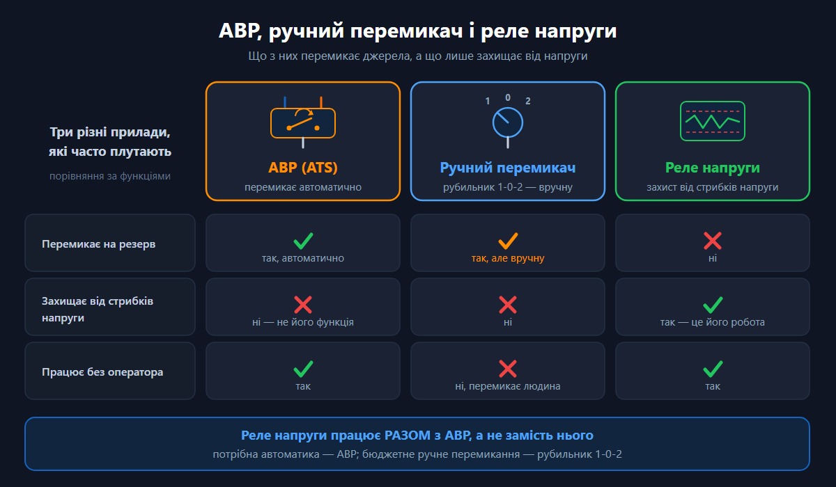
These are three DIFFERENT devices that are often confused. An ATS switches sources AUTOMATICALLY; a manual changeover switch (a 1-0-2 isolator) switches by hand; a voltage relay does not switch sources at all, but protects against over- and undervoltage. Below is a clear separation that removes the confusion when choosing.
| Device | What it does | Does it transfer to backup? | Does it protect against voltage surges? | Operator required |
|---|---|---|---|---|
| ATS | Automatically switches grid → backup → grid | Yes, automatically | No (that is not its function) | No |
| Manual 1-0-2 changeover switch | Selects the source by hand | Yes, but manually | No | Yes |
| Voltage relay | Disconnects the load when the voltage moves outside the limits | No | Yes | No |
The conclusion for your choice:
if you need automatic backup with no human involvement, that is an ATS. If you want a budget solution with manual switching and you are prepared to throw the isolator yourself, that is a 1-0-2 load transfer switch. If the task is to protect equipment from voltage "surges" in the grid, you need a separate voltage relay, which works together with the ATS rather than instead of it. More on how a voltage relay works alongside the rest of the panel is in our guide to the voltage relay, while the automatic and manual options are compared in a separate article about the backup power transfer switch.
How to choose an ATS by rated current
The main selection parameter is the rated operating current (In). The rule is simple: the rating of the ATS must be no lower than the rating of the main breaker and no lower than the calculated load current, with a margin of 20-30% [10]. An undersized rating leads to overheated contacts; an oversized one, to unnecessary expense.
How to calculate the load current
The current is calculated from the load power. For a single-phase supply (230 V): I = P / (U × cosφ). For a three-phase supply (400 V): I = P / (√3 × U × cosφ), where P is the power in watts, U is the voltage and cosφ is the power factor (0.9-1.0 is assumed for domestic loads) [6].
After the calculation a margin of 20-30% is added (closer to 30% if the load includes motors, compressors or pumps with high inrush currents) and the result is rounded up to the nearest standard rating: 25, 32, 40, 63, 100, 125 A [6].
| Example | Power | Calculation | Current with margin | Rating chosen |
|---|---|---|---|---|
| Single-phase house | 5 kW, 230 V, cosφ = 1 | I ≈ 21.7 A | ≈ 28.2 A | 32 A |
| Single-phase house | 11 kW, 230 V, cosφ = 1 | I ≈ 47.8 A | ≈ 62 A | 63 A |
| Three-phase facility | 15 kW, 400 V, cosφ = 0.9 | I ≈ 24.1 A | ≈ 31 A | 32 A |
| Three-phase facility | 30 kW, 400 V, cosφ = 0.9 | I ≈ 48.1 A | ≈ 62 A | 63 A |
The examples are calculated with the formula I = P / (U × cosφ) and rounded to the standard series of ratings [7]. Always agree the specific rating with the power supply design and with the main breaker.
⚠ Important: for most private houses a 63 A ATS is sufficient; for high-power properties and three-phase supplies with a substantial load, 100 A and above is required. Base your choice not only on the average power, but also on the inrush currents of motors.
How many poles to choose: 2P, 3P or 4P
The number of poles is determined by the type of supply and by whether the neutral conductor has to be broken. 2P — for a single-phase supply (line + neutral). 3P — for a three-phase supply without breaking the neutral. 4P — for a three-phase supply with a switched neutral (three lines + neutral).
Whether the neutral has to be broken (4P versus 3P)
Breaking the neutral conductor (4P for a three-phase supply, 2P for a single-phase one) is mandatory when the backup source is a separately derived system — that is, the generator has its own neutral earthing, not connected to the earthing of the grid [8]. Without breaking N, a parallel neutral earth is created: current can circulate through the PE protective conductor, which disrupts the operation of the RCD and is dangerous.
In the typical Ukrainian TN-C-S earthing arrangement, the PEN conductor is split at the house entry into a working neutral (N) and a protective conductor (PE), while the grid neutral is solidly earthed at the substation. For a private generator with its own earth electrode, 4P (three-phase) / 2P (single-phase) is recommended, so that the grid neutral is not connected to the generator neutral [9].
| Supply type | Backup source | Recommended pole configuration |
|---|---|---|
| Single-phase 230 V | Generator (separately earthed) | 2P (with switched neutral) |
| Three-phase 400 V | A second grid supply | 3P (shared neutral) or 4P |
| Three-phase 400 V | Generator (separately earthed) | 4P (with switched neutral) |
Do not write "always 4P" into a design. The need to break the neutral depends on the earthing arrangement and on the type of backup source. For two supplies from the same grid with a single earthed neutral, breaking the neutral may be unnecessary, whereas for a standalone generator it is mandatory. The decision is taken by the designer on the basis of the specific earthing arrangement.
Which ATS you need for a house, an apartment and a business
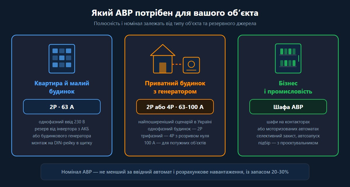
The choice of ATS depends on the property: for an apartment or a small house a single-phase switch rated 63 A is enough; for a three-phase house with a generator, a 4P device rated 63-100 A; for commercial facilities, more powerful industrial solutions. Below are the guidelines by type of consumer.
An ATS for an apartment and a small house
In an apartment, backup power is usually provided by an inverter with a battery or by a shared building generator. For a single-phase supply a 2P switch rated 63 A is suitable — it covers a typical apartment load (lighting, refrigerator, router, chargers). The switch is mounted on a DIN rail in the apartment panel.
An ATS for a private house with a generator
This is the most common scenario in Ukraine. For a single-phase house it is 2P; for a three-phase one, 4P with a switched neutral (if the generator is separately earthed). A 63 A rating covers most houses, while for high-power properties with pumps, heat pumps or electric heating a 4P device rated 100 A is chosen. The details of connecting a generator safely are covered in a separate material on the ATS wiring diagram for a generator and an inverter.
An ATS for business and industry
Commercial and industrial facilities need solutions with a longer service life and higher currents: ATS cabinets built on contactors or on motorised circuit breakers, with selective protection and, where required, generator auto-start. Here a designer must always be involved in the selection, and the installation is agreed with the distribution system operator.
Which UEC SB-ATS series switch to choose
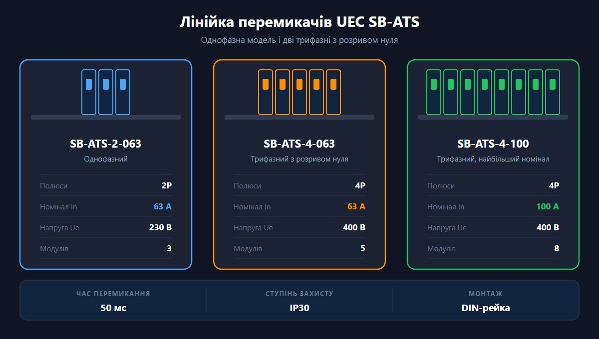
UEC manufactures three models of SB-ATS automatic transfer switches with a common transfer time of 50 ms, DIN-rail mounting and IP30 degree of protection. All three models have automatic and manual modes, a data sheet, a declaration and a certificate — this is confirmed manufacturer documentation.
| Model | Poles | Rated current In | Voltage Ue | Modules | Supply type |
|---|---|---|---|---|---|
| SB-ATS-2-063 | 2P | 63 A | 230 V | 3 | Single-phase |
| SB-ATS-4-063 | 4P | 63 A | 400 V | 5 | Three-phase with switched neutral |
| SB-ATS-4-100 | 4P | 100 A | 400 V | 8 | Three-phase, the highest rating |
The data is given from the UEC manufacturer data sheets. All models: transfer time 50 ms, IP30, DIN-rail mounting, temperature range -5...+40 °C, one-year warranty.
How to choose between the models:
- SB-ATS-2-063 — for a single-phase house or apartment with a backup supply or a 230 V generator.
- SB-ATS-4-063 — for a medium-power three-phase facility with a switched neutral.
- SB-ATS-4-100 — for three-phase houses and facilities with an increased load, where a current margin is needed.
At UEC, as the manufacturer, we equip panels with exactly these switches, and we see that the residential sector most often takes the 63 A models, while the 100 A version goes to high-power houses with electric heating and pumping equipment. The full range is in the automatic transfer switches (ATS) category. To build a backup supply alongside an ATS, 1-0-2 isolators and load transfer switches and contactors are frequently used.
Connecting an ATS in the panel: a general overview
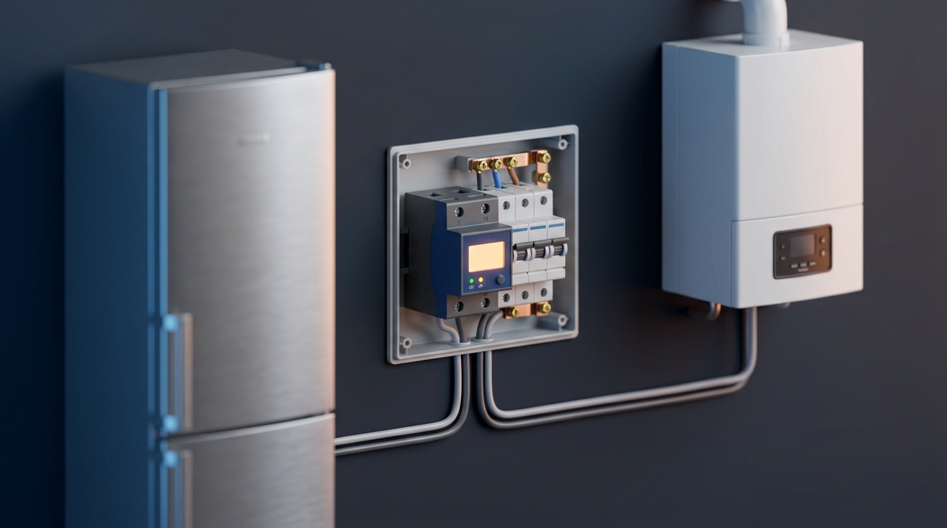
An ATS is installed in the panel after the main breaker and the meter, ahead of the group breakers. The switch has two groups of input terminals (main and backup source) and one group of output terminals (to the load). The exact diagram depends on the type of backup source and on the earthing arrangement.
The general sequence (without detail — the full diagrams are given in separate materials of this series):
- Main breaker → meter → the "grid" input of the ATS.
- Backup source (generator/inverter) → the "backup" input of the ATS through its own protective breaker.
- ATS output → group breakers, RCDs, the load.
- Earthing of the enclosure and coordination of the neutral according to the earthing arrangement.
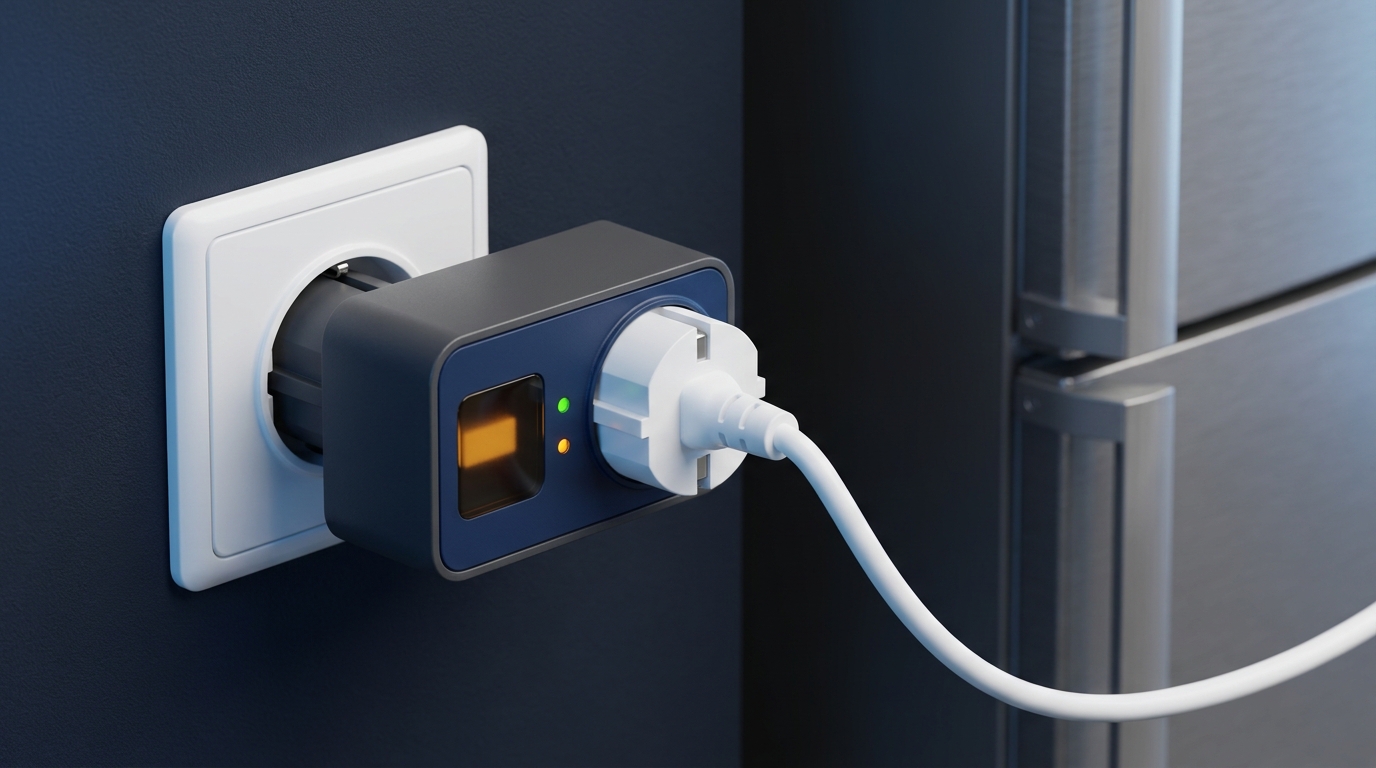
⚠ Critical safety requirement: a generator must never be connected directly into a socket. The resulting backfeed travels out into the external grid and is lethally dangerous for electricians, who may believe the line is de-energised. A backup source may be connected ONLY through a load transfer switch — automatic (ATS) or manual — with mechanical interlocking on the break-before-make principle [2][3].
Step-by-step wiring diagrams with conductor colour coding are covered in the article on the ATS wiring diagram for a generator and an inverter, while typical installation mistakes and the rules for operating an ATS are covered in the material on common ATS operating mistakes.
Standards and requirements: the PUE and IEC 60947-6-1
In Ukraine, backup power supply is governed by the Electrical Installation Code (PUE): automatic transfer of the backup supply falls under automation equipment (PUE, chapter 3.3 "Automation and telemechanics"), while the classification of electrical loads by supply reliability is set out in chapter 1.2. Automatic transfer switching equipment complies with the international standard IEC 60947-6-1 (harmonised as DSTU IEC 60947-6-1).
The key regulatory points:
- PUE, chapter 3.3 "Automation and telemechanics" — governs automatic transfer of the backup supply (ATS); the classification of electrical loads by reliability category is in chapter 1.2 [2].
- IEC 60947-6-1 / DSTU IEC 60947-6-1 — the standard for transfer switching equipment (TSE), that is, equipment for automatic and manual transfer of the load between sources [1].
- Earthing of the generator — a copper protective conductor to the main earthing busbar with a cross-section of at least 10 mm² (for a separately routed unprotected conductor under PUE-7, section 1.7; aluminium — 16 mm²); the resistance of the source neutral earth electrode for a 380/220 V network must be no more than 4 ohms; the generator is placed at least 6 m away from walls with windows and doors because of exhaust gas discharge [11].
- Agreement with the distribution system operator — connecting your own backup source with the ability to operate in parallel with the grid requires approval.
⚠ Important: check the specific editions of the standards and codes currently in force against official sources (UkrNDNC, the Ministry of Energy) before designing. Codes are updated, and responsibility for the compliance of a design lies with the design organisation.
Frequently asked questions about ATS (FAQ)
❓ What is an ATS in simple terms?
An ATS (automatic transfer switch) is a device that switches the supply from the grid to a backup source (a generator, an inverter, a second incoming supply) by itself when the voltage disappears, and switches it back when the grid is restored. Nobody has to operate anything by hand [1].
❓ How does an ATS differ from a manual changeover switch?
An ATS switches sources automatically within seconds, whereas a manual changeover switch (a 1-0-2 isolator) requires a person to physically move the lever. An ATS is more expensive, but it works without anyone present — which is critical when the power goes out at night or while you are away.
❓ Which ATS do you need for a house with a generator?
For a single-phase house it is a 2P switch; for a three-phase house with a separately earthed generator, 4P with a switched neutral. A 63 A rating covers most houses; for high-power properties with electric heating and pumps, 100 A is chosen [10].
❓ How many poles should you choose — 2P or 4P?
2P is for a single-phase supply (line + neutral). 4P is for a three-phase supply with a switched neutral, when the generator is a separately earthed source. The need to break the neutral depends on the earthing arrangement, so the final decision is taken by the designer [8][9].
❓ Can you plug a generator into a socket?
Categorically not. It creates backfeed into the external grid and is lethally dangerous for electricians. A backup source is connected only through an ATS or a manual changeover switch with mechanical interlocking [2][3].
❓ What transfer time is considered normal?
Electronic (static) ATS units transfer in up to 50 ms (for critical loads, no more than 100 ms); motorised devices take from hundreds of milliseconds to 1-2 seconds. UEC SB-ATS series switches have a transfer time of 50 ms in automatic mode [4].