Article Contents
Wiring Diagram for a Magnetic Starter and Contactor: Start-Stop, Thermal Relay, Reversing


Key takeaways
A contactor wiring diagram consists of two circuits: the power circuit, which runs from the protective device through the main contacts to the load, and the control circuit, which feeds coil A1-A2 through a switch or push buttons with their own protection. A magnetic starter is a contactor together with a thermal overload relay, and a three-phase motor is connected through it using the "start-stop" diagram: the "Start" button is bypassed by an auxiliary normally open contact, while the "Stop" button and the normally closed contact of the thermal relay are in series in the coil circuit.
For reversing, two contactors swap two phases, and the mutual mechanical and electrical interlock prevents them from switching on at the same time. The contactor itself protects nothing, so a protective device is always installed ahead of it, and for the UEC SB-PC the datasheet requires gG fuses. Below you will find three diagrams with terminal numbers, the selection of the thermal relay, installation, and checks before the first switch-on.
Hi, I'm Oleh Lukianchuk, an electrical engineer at UEC. I specialize in contactors, motor control circuits and panel equipment.
In this article I will explain how to wire a contactor and a magnetic starter using the "basic", "start-stop" with thermal relay and reversing-with-interlock diagrams, how to choose motor overload protection, install the device and check it before the first start.

Warning! Working with electrical equipment is life-threatening!
Installing contactors and connecting motors are high-hazard work. Work in the panel and on the terminals is carried out with the power off, after mandatory verification, with a voltage indicator, that no voltage is present. Connection to the mains and changes to control diagrams must be made only by an authorized electrician with electrical safety qualification group III or higher. Do not disable the thermal relay, do not remove the interlocks of reversing and automatic transfer switch (ATS) circuits, and do not replace protective devices with jumpers.
Contactor wiring diagrams
The main contacts of a contactor are installed downstream of the protective device, while coil A1-A2 is fed through a switch or push buttons with their own control circuit protection.
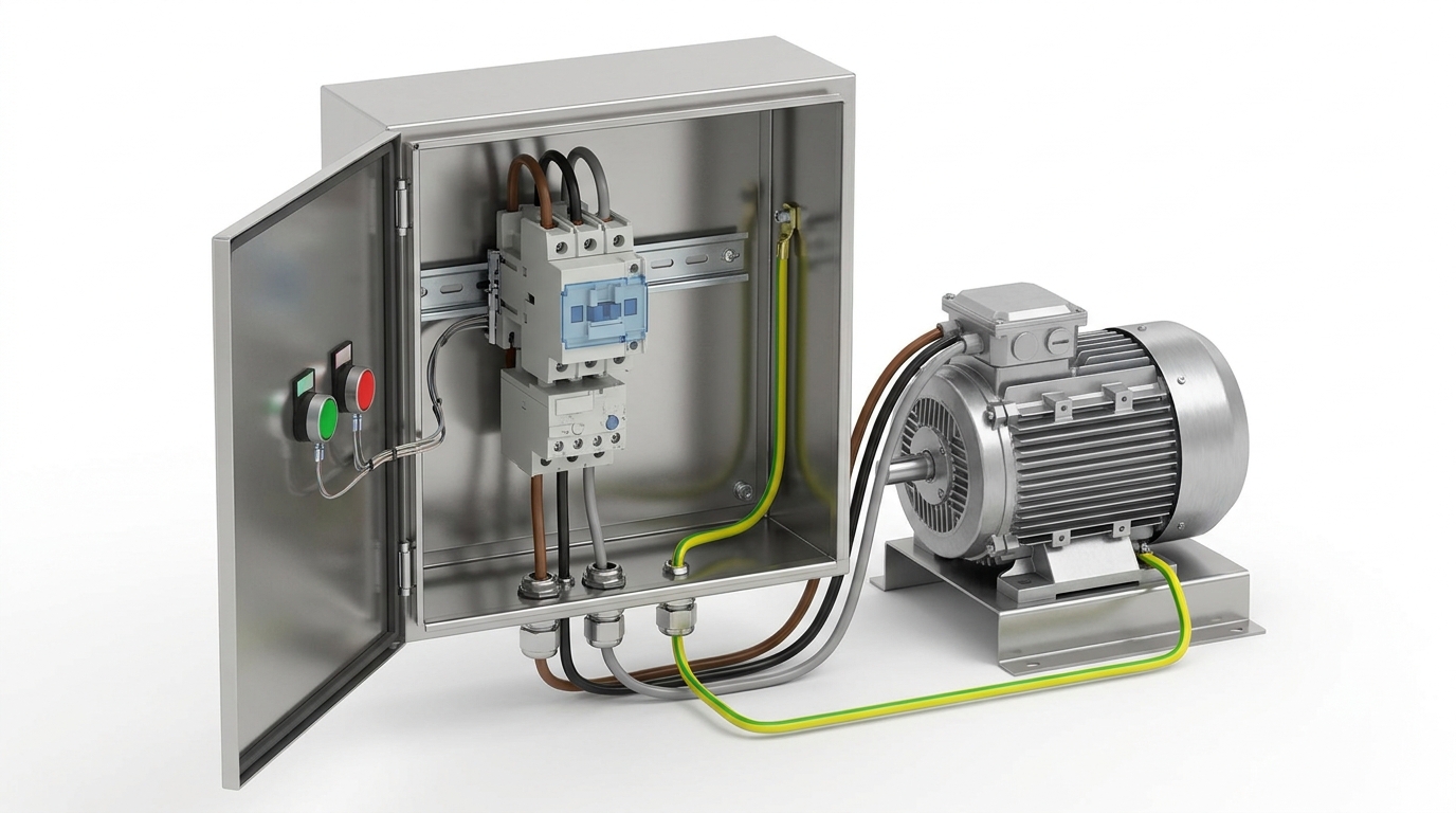
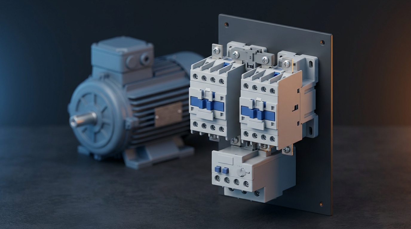
Magnetic starter: contactor, thermal relay and control buttons
Each diagram consists of a power circuit and a control circuit, and in both circuits the protection is provided separately. The colors of the phase and of the control circuit on the diagrams are illustrative: the phase is shown in red, the control circuit in gray, while neutral is blue and the protective conductor is yellow-green, as with the insulation of the conductors.
The contactor is designated KM1, the protective device in the power circuit is QF1 (on the SB-PC diagrams, fuses FU1), the control circuit protection is QF2 (or fuse FU2), and the thermal relay is FR1. The terminals are designated according to the standard: coil A1-A2, main contacts 1/L1-2/T1, 3/L2-4/T2, 5/L3-6/T3, auxiliary contacts 13-14 and 21-22, thermal relay 95-96.
The control buttons are shown generically, because they are selected separately according to the control circuit voltage and the number of contacts, while in the SB-CMS enclosure they are already included. The full table of designations for SB-PC, SB-AC, SB-ATD, HC and CTR is given in the article on contactor terminal designations.
How to connect a contactor: basic diagram via a circuit breaker and a switch
The main contacts are installed downstream of the protective device, and the coil is fed through a switch whose voltage matches that of the coil.
The basic wiring diagram of a three-phase contactor consists of two circuits. The power circuit runs from QF1 (or fuses FU1) through the main contacts KM1 to the load, while the control circuit takes the phase after QF1, passes it through its own circuit breaker QF2 and switch SA1 to terminal A1 of the coil, and terminal A2 is connected to neutral taken from the mains side, ahead of the contactor. When SA1 is closed, the coil receives voltage and the load switches on, and when it is open, the load switches off. This two-wire control diagram is simple but has one drawback: if the switch remains closed, the contactor will switch on by itself when voltage returns.
Two-wire control suits heaters and lighting, where an automatic restart creates no hazard, while motors, in particular fans near which people may be present, require a diagram with self-holding and a thermal relay.
The coil voltage must match the control circuit voltage: a 230 V coil is connected between phase and neutral, and a 400 V coil between two phases through a two-pole QF2. For UEC SB-PC contactors the datasheet requires gG fuses connected in series, of the appropriate rating, so the SB-PC diagrams show these fuses, while for modular HC and CTR the protective device is selected according to the cable cross-section. The control circuit has its own protection because it is wired with thin conductors, which the protective device of the circuit does not protect.
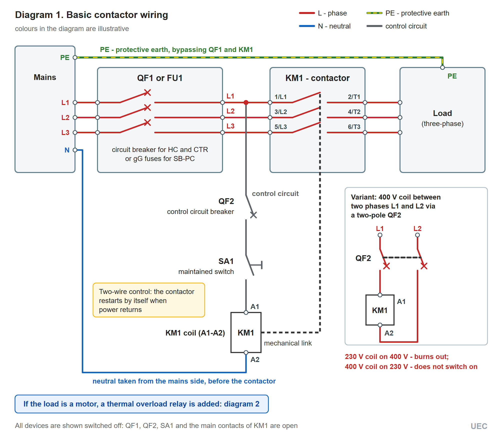
Contactor wiring diagram: power circuit through QF1 and KM1, control circuit through QF2 and switch SA1
Magnetic starter wiring diagram with a thermal relay
The wiring diagram of a three-phase motor through a magnetic starter is built as follows: the "Start" button is bypassed by an auxiliary normally open contact, while the "Stop" button and the normally closed contact of the thermal relay are in series in the coil circuit.
In the power circuit, fuses FU1 feed contactor KM1; thermal relay FR1 is connected to its output terminals 2/T1, 4/T2, 6/T3, and motor M1 is fed from the relay. According to its product card, the SB-TOR relay is compatible with the SB-PC and is installed between the contactor and the motor. In the control circuit, the following are in series: fuse FU2, the relay's normally closed contact 95-96, the "Stop" button SB1 with a normally closed contact, and a section of two parallel branches: the "Start" button SB2 with a normally open contact, and the auxiliary normally open contact KM1 13-14. Next in the circuit are coil A1-A2 and neutral, and the operating sequence of the diagram is as follows.
- Pressing "Start" closes the coil circuit, the contactor pulls in, the main contacts switch the motor on, and contact 13-14 closes in parallel with the button.
- After "Start" is released, the coil current flows through contact 13-14, and the contactor holds itself in; this is self-holding.
- Pressing "Stop" breaks the circuit, the coil is de-energized, contact 13-14 opens, and after "Stop" is released the motor does not start.
- In case of overload the relay opens contact 95-96, the coil is de-energized, and the motor switches off; after the relay cools down, the motor does not restart by itself, and "Start" must be pressed again.
- If the voltage disappears, the contactor drops out, and after the voltage returns the motor stays off.
This behavior is zero-voltage protection: it prevents an unexpected start after voltage is restored, after the thermal relay is reset, or after an emergency stop. The name "zero-voltage protection" refers specifically to the self-holding diagram, not to the contactor as a device, because two-wire control from a switch does not have this property.
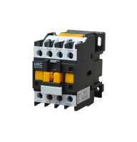
Self-holding requires a normally open contact 13-14: the SB-PC for 9-32 A comes with one built-in auxiliary contact, either normally open "1NO" or normally closed "1NC", and only the "1NO" version or an additional SB-AC contact is suitable for self-holding. The thermal relay is set to the motor's rated current from the nameplate: neither higher nor lower than this value, and automatic reset of the relay is permitted only with three-wire control, because with two-wire control the motor will start by itself after cooling down.
For the SB-PC, the datasheet permits operation only with gG fuses, so the power circuit of diagram 2 shows these fuses (FU1), not a circuit breaker. The control circuit passes through auxiliary contacts for which the datasheets require a gG fuse: 10 A for the built-in auxiliary contact of the SB-PC, 12 A for the auxiliary contacts of SB-AC and SB-ATD add-on blocks, and 5 A for the auxiliary contacts of the SB-TOR thermal relay.
Since the FU2 circuit contains the relay's normally closed contact 95-96, fuse FU2 is taken as 5 A per table 3 of the SB-TOR datasheet: this is the smallest of the ratings 5, 10 and 12 A. The FU1 rating is taken from the SB-PC datasheet table and according to the cable cross-section. For modular HC and CTR, the control circuit is protected by a separate low-rated circuit breaker.
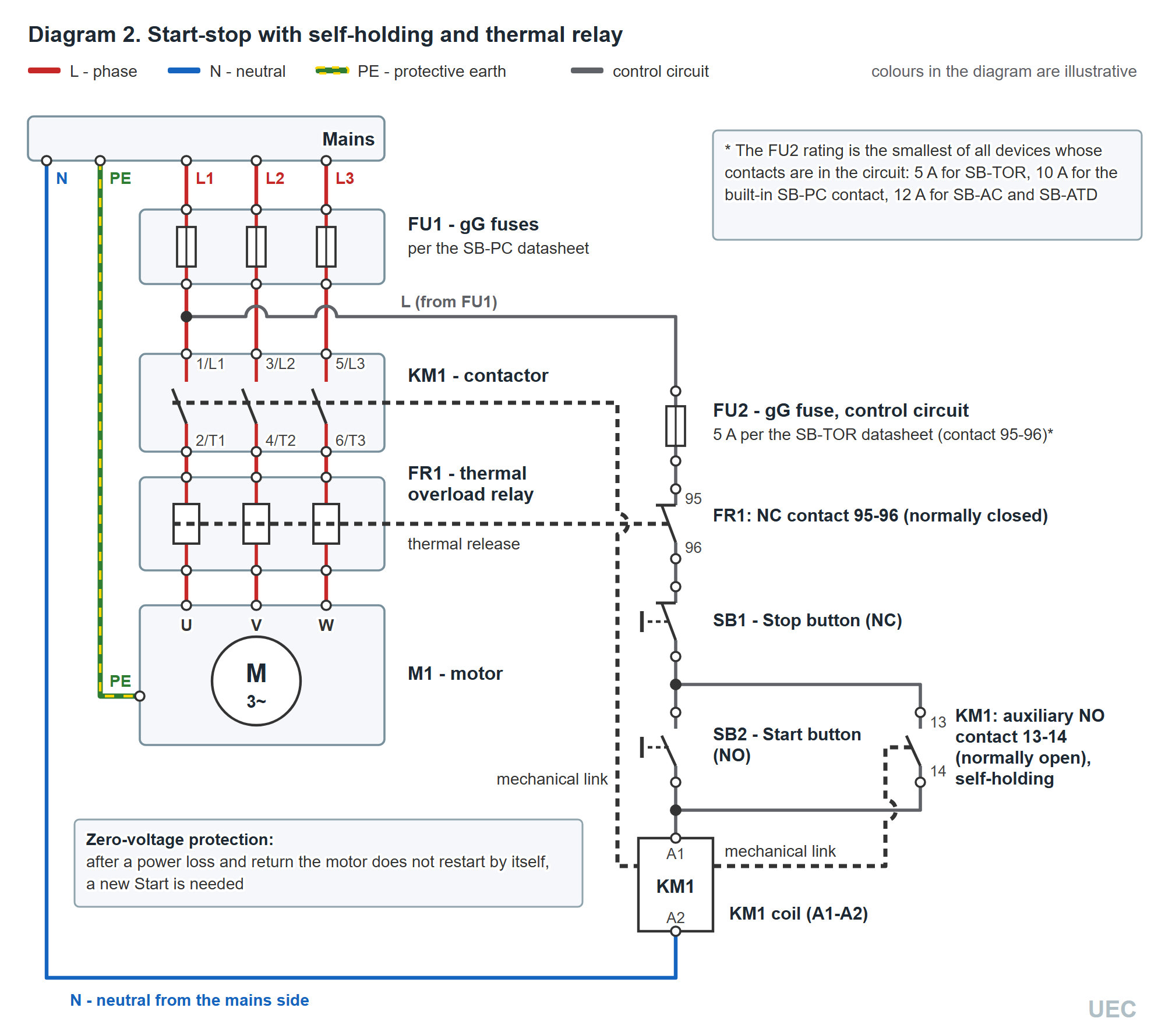
Magnetic starter wiring diagram: "start-stop" with self-holding, normally closed contact of the thermal relay in the coil circuit
Reversing contactor wiring diagram with interlock
For reversing, two contactors swap two phases, and the mutual interlock prevents them from switching on at the same time.
A reversing assembly consists of two identical contactors, each rated for the full motor current: KM1 runs the motor forward, while two phases, for example L1 and L3, are swapped on the input terminals of KM2, so the motor runs in reverse. The outputs of both contactors are tied together terminal to terminal, and a common thermal relay FR1 follows them.
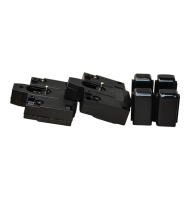
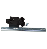
If both contactors switch on together, a short circuit between phases will occur through their contacts, so two types of interlock are used. The electrical interlock is implemented with normally closed contacts: the normally closed contact of KM2 is placed in series in the coil circuit of KM1, and the normally closed contact of KM1 in the coil circuit of KM2. The mechanical interlock is an add-on block between the contactors that physically prevents both from closing.
Each contactor has its own self-holding through a normally open contact, while fuse FU2, the thermal relay's normally closed contact 95-96 and the "Stop" button remain common to both branches. For the SB-PC for 9-32 A with one built-in auxiliary contact this is not enough: both a normally open contact for self-holding and a normally closed one for the mutual interlock are needed, so an SB-AC is added to each contactor. Fuse FU2 in the diagram with the SB-TOR thermal relay is taken as 5 A, that is, according to the smallest of the ratings 5, 10 and 12 A that the datasheets specify for the contacts in this circuit.
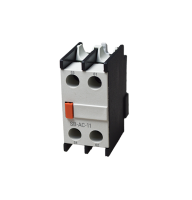
The terminal numbers depend on the version: the SB-PC for 40-95 A has both contacts built in, 13-14 (normally open, NO) and 21-22 (normally closed, NC), while the SB-PC for 9-32 A has only one built in, and the second is taken from the SB-AC-11 - 53-54 (NO) and 61-62 (NC). UEC offers separate mechanical interlocks for the SB-PC for 9-32 A and for 40-95 A.
Reversing should be done after the motor has come to a complete stop, because switching "on the fly" is category AC-4 duty, and according to the SB-PC datasheet the rated AC-4 currents are much lower than the AC-3 currents; for mechanisms with high inertia, a time delay is introduced between "Stop" and the start in the opposite direction. For currents of 115-630 A, reversing is done with ready-made SB-PCR reversing contactors.
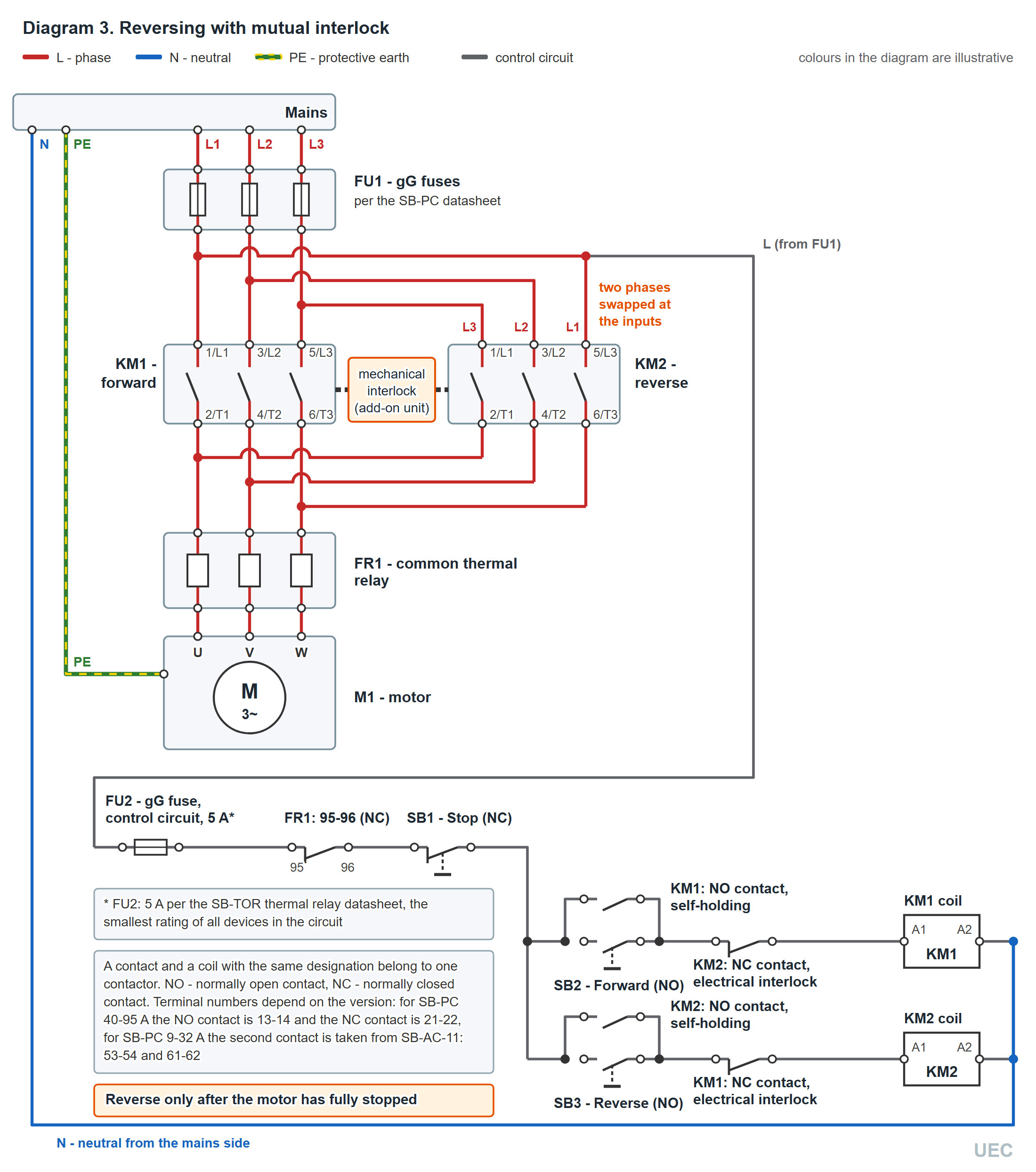
Reversing contactor wiring diagram: two phases swapped, electrical and mechanical interlock of the contactors
What to build a magnetic starter from: a thermal relay, a ready-made SB-CMS or a motor protection circuit breaker
A starter is assembled from an SB-PC contactor and an SB-TOR thermal relay; alternatively, you take a ready-made SB-CMS in an IP54 enclosure or, for motors up to 32 A, install a GEWISS motor protection circuit breaker (MPCB) paired with a contactor.
All three options perform the same task: the contactor switches the motor, and a separate device protects the winding from overload. An open assembly of two devices suits panel mounting, while a ready-made starter shortens the selection of compatible parts and the installation. A contactor and a thermal relay do not protect against short circuit, so an upstream protective device is installed ahead of the SB-PC and SB-CMS, and for the SB-PC the datasheet requires a gG fuse. The GEWISS MPCB provides overcurrent protection in all poles, and the "MPCB - contactor" pair is matched according to the documentation of both manufacturers.
SB-TOR thermal relay: motor overload protection
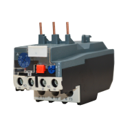
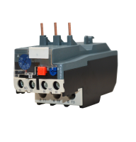
The SB-TOR thermal relay protects the motor against overload, phase imbalance, prolonged starting and rotor jamming. The setting is chosen according to the motor's rated current.
In the UEC catalog, SB-TOR thermal relays are available in 22 setting ranges: from 0.1-0.16 A to 80-93 A. Each relay has three poles, one normally open and one normally closed auxiliary contact, a rated voltage Ue of 400 V, and according to its product card is compatible with SB-PC contactors. The normally closed contact of the thermal relay is connected in series in the contactor coil circuit, and the normally open one can be used for signaling. The range is chosen so that the motor's rated current from the nameplate falls within the relay's setting range.
A thermal relay responds to heating, so it does not protect against short circuit: that is the job of the protective device ahead of the contactor, and for the SB-PC, of a gG fuse per the datasheet. That is why a typical motor starter assembly consists of three stages: short-circuit protection, a contactor for switching, and a thermal relay against overload. The trip class and the reset method are not given in the SB-TOR product cards, so these parameters are determined from the relay documentation. The thermal relay is not taken out of service and its setting is not raised above the motor current from the nameplate, because in that case the motor winding will burn out from overload before any other protection operates.
SB-CMS as a ready-made magnetic starter in an enclosure
The SB-CMS combines a contactor, a thermal relay and control buttons in an IP54 enclosure, so it is a ready-made starter for construction sites and workshops.
This illustrates the difference between a contactor and a starter: the SB-PC contactor and the SB-TOR relay are assembled from two devices, while in the SB-CMS they are already in one enclosure together with the control buttons. The SB-CMS 9 A contactor is rated 4 kW at AC-3 and 400 V, with a 220 V coil and a thermal relay setting of 7-10 A, and the SB-CMS 25 A is rated 11 kW with a setting of 17-25 A. According to the datasheet, SB-CMS series contactors are intended for remote starting and stopping of three-phase squirrel-cage induction motors up to 400 V and for motor overload protection, and they operate at an ambient temperature from minus 5 to plus 40 °C. The ready-made version shortens the selection of compatible parts and the installation, but short-circuit protection of the circuit ahead of it is still required.
GEWISS motor protection circuit breaker and contactor: an alternative to the thermal relay
Up to 32 A, a GEWISS MPCB paired with a contactor is used instead of a thermal relay: the MPCB protects the motor, and the contactor switches it on when commanded.
The catalog contains GEWISS motor protection circuit breakers in 15 ranges from 0.1-0.16 to 25-32 A. These are three-pole devices 2.5 modules wide, with a degree of protection of IP20, overcurrent protection in all poles and an operating temperature from minus 25 to plus 60 °C. The product card of the 6.3-10 A version states a terminal tightening torque of 2 N·m, a flexible conductor cross-section of up to 6 mm2 and a rigid one of up to 10 mm2, and an electrical endurance of at least 100 000 cycles. An auxiliary contact 1NO+1NC, half a module wide, is available for the MPCB. The trip class and breaking capacity are not given in the cards, so they are clarified from the manufacturer's documentation, and the matching of the "MPCB - contactor" pair for short-circuit coordination is verified against the documentation of both manufacturers.
Contactors in industrial circuits: motors, pumps, ventilation and ATS
In an industrial circuit, the contactor switches the motor on, a circuit breaker or fuse protects the circuit against short circuit, the thermal relay protects the motor against overload, and the "Start" and "Stop" commands are given by push buttons.
A typical motor control unit consists of four parts: a short-circuit protective device (a circuit breaker, or gG fuses according to the datasheet for SB-PC), a contactor for switching, a thermal relay against overload, and a control circuit with the "Start" and "Stop" buttons. For a pump, fan or compressor this set is enough if the motor is started direct-on-line and the load is steady. From the UEC and GEWISS range, such a unit is assembled from SB-PC or SB-CMS contactors, SB-TOR thermal relays or GEWISS MPCBs, SB-AC auxiliary contacts and the UEC RT time relay. For reversing the motor, this unit is duplicated according to diagram 3: two contactors with electrical and mechanical interlock.
What do you need, besides a contactor, to connect a motor?
A motor needs a short-circuit protective device, a contactor, a thermal relay or an MPCB, and a control circuit with its own protection.
The short-circuit protective device comes first and protects the cable and the motor. For SB-PC the datasheet allows only gG fuses, and the pairing "GEWISS MPCB - contactor" is coordinated according to the manufacturers' documentation. The starting current of a motor is several times higher than its running current, so the trip characteristic (curve) of the circuit breaker is chosen so that it does not trip the circuit during starting, and the rating of a fuse must not exceed the datasheet value. Selection of a protective device for a three-phase circuit is covered in the articles on three-pole and four-pole circuit breakers and on a circuit breaker for 380 volts.
Next comes the contactor, which switches the motor, and the thermal relay, which is connected in the circuit between the contactor and the motor. For motors up to 32 A, a GEWISS MPCB is used instead of the relay. The control circuit has its own protection and contains the "Start" and "Stop" buttons and the normally closed contact of the thermal relay. The types and purposes of fuses are described in the overview of fuse types, and the gG class for SB-PC is specified in the contactor datasheet. If the circuit breaker still trips during starting, the causes and diagnostics are given in the article on nuisance tripping of a circuit breaker.
In a three-phase network, supply monitoring is added to this set. A phase loss or a voltage imbalance is dangerous for the motor, and the SB-TOR thermal relay, according to its product card, responds to phase imbalance. Protection of a three-phase network by phase monitoring relays and voltage relays is covered in the article on three-phase voltage relay and phase monitoring. The SB-TOR thermal relay does not replace this: it responds to the motor current, not to the mains voltage.
Why does star-delta starting need three contactors?
One contactor connects the motor to the mains, the second connects the windings in star, the third in delta.
Star-delta starting reduces the starting current of a three-phase motor to one third of the direct-on-line starting current: first the windings are connected in star, and after run-up a time relay switches them to delta. This requires a line contactor KM1, a star contactor KM2, a delta contactor KM3, a time relay and a thermal relay. The delay is produced by a time relay, for example the UEC RT. Contactors KM2 and KM3 are interlocked with each other electrically by normally closed contacts and mechanically, because without the interlock a phase-to-phase short circuit occurs, and a short pause is needed between opening the star and closing the delta.
The method has limitations: it requires a motor with six accessible winding terminals whose winding in delta is rated for the mains voltage. For a 400 V network this is a motor with a nameplate rating of 400/690 V, while a 230/400 V motor in such a network permanently runs in star and is not suitable for this method. The starting torque in star is also reduced: theoretically to one third, and in practice even less, so the method is suitable for light-duty starting of fans and pumps, not for loads that need a high starting torque. The full diagram with interlocks and time delay is taken from the documentation for the contactors and time relays.
Why does an ATS on two contactors need mutual interlocking?
Without interlocking, both sources can end up in one circuit, so an ATS on two contactors is built with mechanical and electrical interlocking, as in reversing.
The main-supply contactor and the backup-source contactor are connected to one load busbar, so their simultaneous closing connects the two sources to each other. The same mutual interlock as in reversing is used for this: mechanical between the devices and electrical through normally closed auxiliary contacts in the coil circuit of each contactor. For household panels there are ready-made ATS units and three-position changeover switches in which connecting the sources to each other is made impossible by design. The operating principle, types and choice between them are covered in the ATS guide and in the comparison "ATS or manual changeover switch"; the SB-PCR reversing contactor product card also lists automatic transfer to a backup supply among its applications.
How to install and check a contactor before the first start?
Installation is carried out with the power off and the absence of voltage verified with a voltage indicator, and before the first switch-on the coil voltage, the interlock circuit and the thermal relay setting are checked.
Installation, cleaning, tightening of terminals and replacement of the contactor are performed only with the power off, because a device under voltage is dangerous. Only measurements, inspection with a thermal imager and tests are permitted under voltage, and they are performed by an authorized electrician with electrical safety qualification group III or higher and the appropriate protective equipment. The contactor is installed on a vertical surface: the SB-PC datasheet permits a deviation from the vertical of up to ±30°, and for other models the position is taken from the product datasheet. Flexible conductors are connected with ferrules, and the cross-section and tightening torque are taken from the documentation of the specific device.
How to install a contactor safely?
The contactor is installed in a de-energized panel on a vertical surface, with the terminals tightened to the torque specified in the device documentation.
Before work starts, the disconnector or circuit breaker suitable for isolation that feeds the contactor (on the mains side) is switched off, the switched-off device is secured against accidental switching on (a lock or a tag), and the absence of voltage is verified with a voltage indicator on every conductor you will touch. Flexible conductors are crimped with ferrules, because a conductor without a ferrule is flattened under the screw and the contact weakens. The tightening torque for SB-PC is 1.2 N·m for 9-25 A, 2.5 N·m for 32-65 A and 4.0 N·m for 80-95 A. For the power terminals of GEWISS CTR, the GEWISS technical catalog specifies 1.2 N·m for CTR 20-32 A and 3.5 N·m for CTR 40 and 63 A. In the CTR product cards on the site, 0.6 N·m is given as the tightening torque of the contact terminals, but according to the GEWISS catalog this value applies to the coil terminals, so the power terminals are not tightened to it.
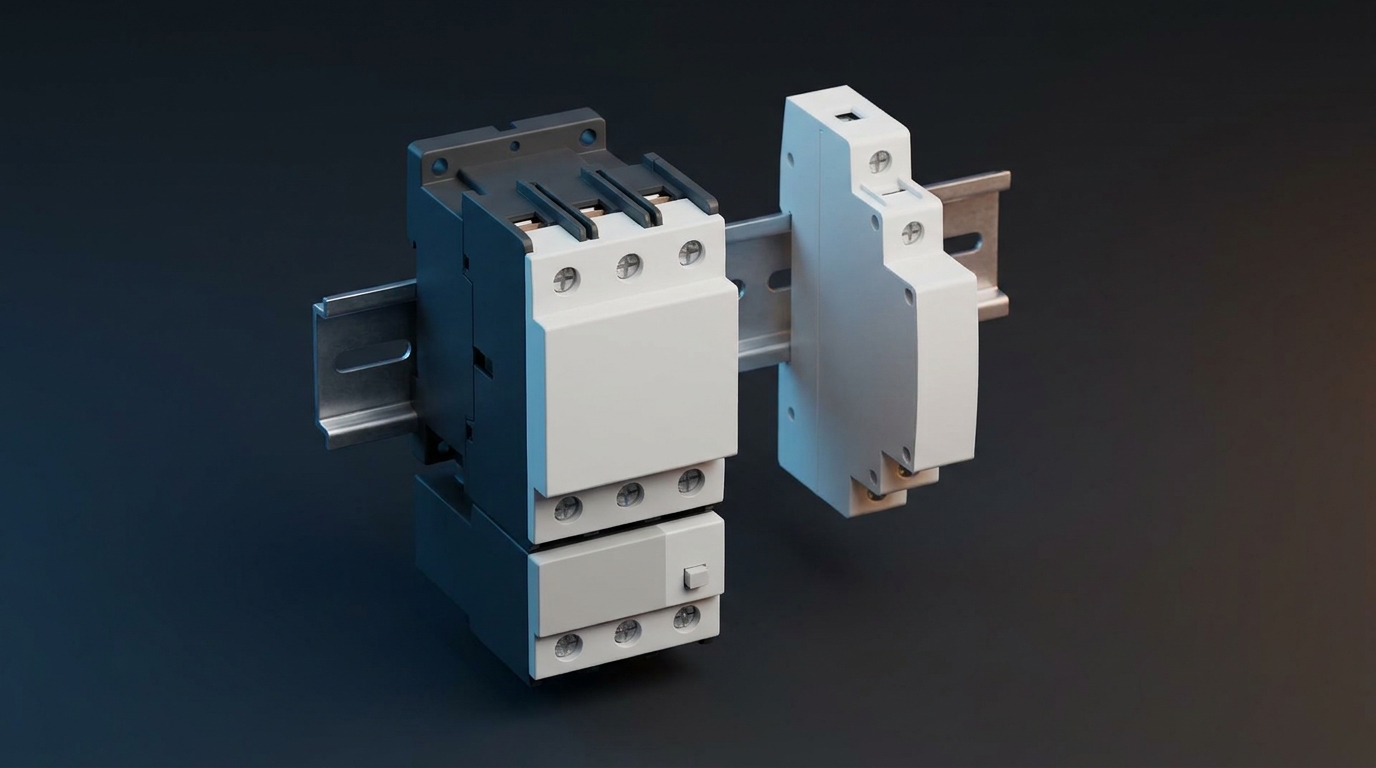
SB-PC contactors are fixed with screws or on a mounting rail, and the ambient air temperature according to the datasheet must be from minus 5 to plus 40 °C. Modular contactors mounted side by side are spaced with gaps: according to the GEWISS catalog, up to three CTR devices can be placed side by side at temperatures up to 40 °C, two at 40-55 °C and one at 55-70 °C, and a spacer plate limits heating. When drilling the panel, the devices are covered to keep metal shavings out, because shavings on the pole faces of the magnetic core cause hum and flashover. According to the datasheet, SB-PC belongs to class 0 under DSTU EN 61140, so it is installed only in a panel or enclosure with no access to the terminals; for the SB-TOR thermal relay the datasheet additionally requires switchgear of protection class I or higher.
What to check before the first switch-on?
Before the first switch-on, the coil voltage, the interlock circuit and the thermal relay setting are checked, and the control circuit is tested with the load disconnected.
The check proceeds from simple to complex, so that an error in the circuit does not damage the motor or create a hazard. Steps 1-7 and 9 are performed on a de-energized device, and voltage is applied only at steps 8 and 10: first to the device with the load disconnected, to check the control circuit, then to the power circuit for a short start. Steps 8 and 10 are performed by an authorized electrician, because this is work under voltage. If any step gives the wrong result, the start is not continued, and the cause is investigated.
- Verify that the voltage and frequency of the coil match the control circuit.
- Check the tightening of all screws and that the installation matches the diagram.
- Check the connection of the protective conductor to the metal enclosure of the device and of the motor.
- Disconnect the motor cable from the output terminals of the thermal relay or the contactor and measure the insulation resistance of the motor and the cable with a megohmmeter, disconnecting any electronics; permissible values are taken from the motor datasheet and the current standards for testing electrical equipment.
- Check the mechanical interlock of the reversing circuit on a fully de-energized device (power circuit and control circuit): according to the UEC datasheet, this is done by pressing the contact carriers of the contactors in turn.
- Set the thermal relay to the rated current of the motor from the nameplate.
- Insulate the conductors of the motor cable disconnected from the output terminals of the thermal relay or the contactor.
- Apply voltage to the device with the motor cable disconnected (the input terminals of the contactor are live), switch the contactor on and off several times and make sure that it operates crisply.
- Remove the voltage, verify its absence with a voltage indicator and only then connect the motor.
- Apply voltage and check the direction of rotation with a short start (preferably with no load on the shaft); to change the direction, remove the voltage again, verify its absence and swap two phases.
Pressing the armature or the contact carrier by hand under voltage is not allowed: it is dangerous for the person and destroys the contacts. Manual closing of the contactor is permitted only on a de-energized device and following the manufacturer's instructions, for example when checking the interlock.
The thermal relay and the reversing interlock are not switched off or bypassed, either during commissioning or later. If the protection gets in the way of operation, the cause of its tripping is investigated rather than the protection itself being removed.
Typical errors in wiring diagrams and in operation
The most dangerous diagram errors are reversing without mutual interlock, the normally closed contact of the thermal relay outside the coil circuit, and a control circuit without its own protection.
An error in the circuit may not show up at no load and appear only under load, during reversing or after a loss of voltage. What such errors have in common is that the circuit, the motor or a person is left without a separate protective device or interlock. Most of them are revealed by the check before the first switch-on, if it is performed completely and in order. A separate group is operating errors, when protection is taken out of service after commissioning.
Errors in diagrams and connection
Diagram errors are missing interlocks, auxiliary contacts used in the wrong role and a thermal relay outside the coil circuit.
Reversing without mutual interlock allows two contactors to switch on at once, and then a phase-to-phase short circuit occurs through their contacts. An auxiliary contact must match its role: self-holding needs a normally open (NO) contact, electrical interlock needs a normally closed (NC) one, and the SB-PC contactor for 9-32 A has only one built-in contact of a single type. A normally closed contact of the thermal relay that is not connected in series in the coil circuit makes the thermal protection ineffective: the motor overheats, and the contactor does not switch off. A typical error in diagrams with the neutral taken through the contactor is to connect coil terminal A2 to the neutral after the contactor pole: with the contactor open, the coil gets no neutral, and the contactor does not switch on.
Another typical error is to feed the control circuit without its own circuit breaker or fuse, in which case a short circuit in the thin conductors of the control circuit is left unprotected. The "Stop" button must be normally closed (NC) and connected in series in the coil circuit: then a broken wire or a failed button switches the motor off rather than leaving it running. The "Start" button is bypassed by an auxiliary normally open contact rather than connected in series with it. The diagram is built so that after a loss of voltage in the control circuit the load switches off and does not switch on by itself after the voltage returns, as in the self-holding diagram, and this needs push buttons and an auxiliary contact, not a latching switch.
Operating errors
Operating errors are a thermal relay taken out of service, a removed interlock and a contactor used as a disconnector.
A thermal relay that is taken out of service or bypassed leaves the motor without overload protection, and increasing the setting above the motor current from the nameplate gives the same result. A removed mechanical or electrical interlock of reversing and ATS turns two sources or two directions of rotation into a potential short circuit. A contactor does not provide isolation, so when servicing a circuit, the voltage is removed with a disconnector or a circuit breaker suitable for isolation on the supply side, the switched-off device is secured against accidental switching on (a lock or a tag), and the absence of voltage is verified with a voltage indicator.
A hum, heating or sticking of the contactor must not be left without attention: they point to a cause that must be eliminated, not to a device that can be "tweaked" by hand under voltage.
Frequently asked questions about starter and contactor wiring diagrams
A magnetic starter is connected using a "start-stop" diagram with self-holding and a thermal relay, and reversing is built on two contactors with mutual interlock.
❓ How does a magnetic starter work and what is it for?
A magnetic starter switches a three-phase motor on and off by means of a contactor and switches it off in case of prolonged overload by means of a thermal relay. The "Start" button applies voltage to the coil, and the auxiliary normally open contact bypasses the button and keeps the starter switched on. The normally closed contact of the thermal relay is in the coil circuit and breaks this circuit in case of overload. After a loss of voltage the motor does not restart by itself, and this is a safety function.
❓ How to connect a thermal relay to a contactor?
The thermal relay is installed between the contactor and the motor: its heating elements are in the power circuit at the contactor output. The normally closed contact 95-96 of the relay is connected in series in the contactor coil circuit, and the normally open contact 97-98 can be used for signaling. The relay is set to the motor's rated current from the nameplate. The SB-TOR relay, according to its product card, is compatible with SB-PC contactors.
❓ Why is self-holding needed in a starter circuit?
Self-holding keeps the contactor switched on after the "Start" button is released: the coil current flows through the auxiliary normally open contact 13-14 connected in parallel with the button. After "Stop" is pressed or the voltage is lost, this contact opens, and the motor does not start by itself after the voltage returns. This is how the diagram performs the zero-voltage protection function. Self-holding specifically requires a normally open contact, so SB-PC for 9-32 A is taken in the "1NO" version or an SB-AC contact is added.
❓ Can a motor be reversed while it is running?
Reversing is performed after the motor has come to a complete stop. Switching a running motor falls into the heavier category AC-4, and the rated currents of SB-PC for AC-4 are much lower than for AC-3. For high-inertia machinery, a time delay is introduced between "Stop" and the reverse start. Both reversing contactors have mutual mechanical and electrical interlock.