Article Contents
Contactor and Magnetic Starter: What They Are, How They Work and Which Types Exist


Key takeaways
A contactor switches a heavy load on and off in response to a weak signal, so it is used to control storage water heaters, underfloor heating, pumps, ventilation and panel automation. The words "contactor" and "magnetic starter" are often used as synonyms, but a magnetic starter consists of a contactor and a thermal overload relay, while the contactor itself does not protect the motor. According to the product page, the modular UEC HC contactors are declared for utilization categories AC-1 and AC-7a, so direct-on-line (DOL) starting of larger motors requires a contactor with utilization category AC-3.
The sections below cover the construction and operating principle, the types of UEC and GEWISS contactors, the difference between a contactor and a starter, and choosing the type for the load. The main rule is this: a contactor protects neither the circuit nor the motor against short circuit and overload; it only carries out a command, while protection is provided separately.
Hi, I'm Oleh Lukianchuk, an electrical engineer at UEC. I specialize in contactors, panel equipment and protection of electrical networks.
In this article I will explain what a contactor is and how it works, which types of UEC and GEWISS contactors exist, how a contactor differs from a magnetic starter and how to choose the contactor type for a load.

Warning! Working with electrical equipment is life-threatening!
Installing contactors and connecting motors are classed as high-hazard work. Work in the panel and on the terminals is carried out with the power off and with a mandatory check, using a voltage indicator, that no voltage is present. Connection to the mains and changes to control circuits may be done only by an authorized electrician with a valid certificate and electrical safety qualification group III or higher. Do not disable the thermal overload relay, do not remove the reversing and automatic transfer switch (ATS) interlocks, and do not replace protective devices with jumpers.
| Contactor type | Utilization categories | Current | Where used | UEC or GEWISS example |
|---|---|---|---|---|
| Modular | AC-1 and AC-7a; for motors: HC - AC-7b up to 20 A, CTR - AC-3 and AC-7b up to 30 A according to the GEWISS catalog | 16-63 A | panel: storage water heater, underfloor heating, lighting, load shedding | UEC HC, GEWISS CTR |
| Power | AC-3, motor power at 400 V 4-335 kW | 9-630 A | motors, pumps, compressors, ventilation | UEC SB-PC |
| Enclosed (IP54) | AC-3 | 9-40 A | construction sites, workshops, a ready-made starter with a thermal relay and control buttons | UEC SB-CMS |
| Reversing | AC-3 | 115-630 A | motor reversing, automatic transfer switch (ATS) | UEC SB-PCR |
What is a contactor and why is it needed?
A contactor is an electromagnetic switching device that switches a load on and off on a signal to its coil. It controls a motor, a heater or a group of circuits, but does not protect them against short circuit.
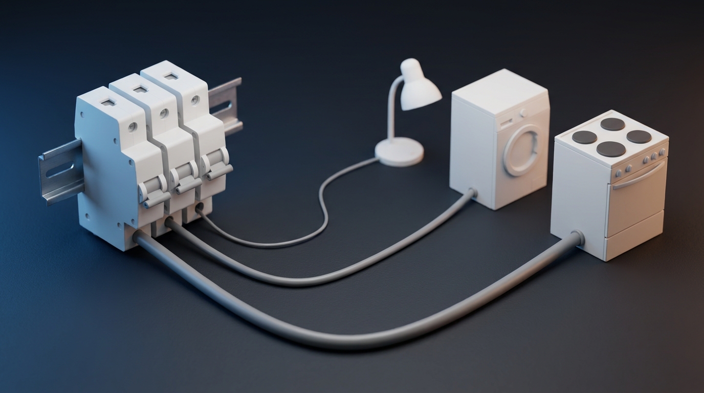
A weak signal in the control circuit, coming from a pushbutton, a timer, a thermostat or a voltage relay, closes the power contacts in the power circuit. Thanks to this, a thin wire with a switch can turn on a storage water heater of several kilowatts or a motor of tens of kilowatts, while the switch itself does not carry the current of the connected load. A contactor is designed for frequent operation on command, unlike a circuit breaker, which is primarily a protective device, although the permissible switching frequency is set by the datasheet of the specific device. In the UEC and GEWISS catalog this task is performed by modular contactors for the panel and power contactors rated 9-630 A.
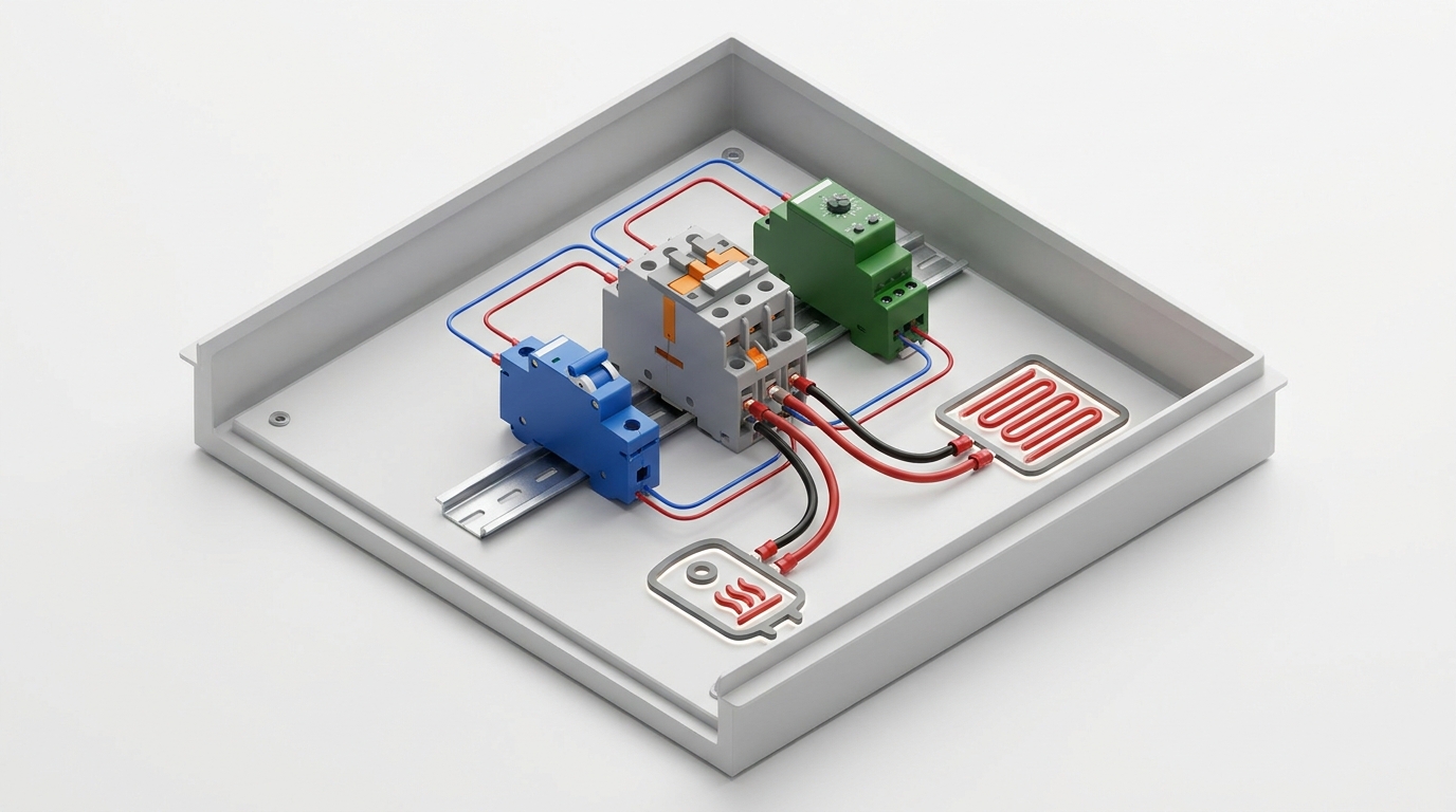
A weak signal controls a heavy load through the contactor
What does a contactor do and how does it differ from a circuit breaker?
A contactor switches a load remotely, while a circuit breaker trips the circuit on overload and short circuit. One device does not replace the other.
A circuit breaker exists for protection: it opens the circuit on overload and short circuit, and its endurance in cycles is much lower than that of a contactor. The product page of the UEC SB-M9 breaker states at least 10 000 cycles of electrical and 20 000 cycles of mechanical endurance. A contactor is built for frequent switching on command: according to the datasheet of the UEC SB-PC contactor rated 9-25 A, electrical endurance under AC-3 is 2.1 million cycles, and mechanical endurance is 15 million cycles at 9-18 A and 12 million cycles at 25 A. A load that is switched on automatically every day should be connected through a contactor, while the circuit breaker remains the protection of the circuit ahead of it.
How does a contactor differ from a relay, a knife switch and a magnetic starter?
A relay switches a weak signal, a knife switch is operated by hand, and a magnetic starter is a contactor together with a thermal overload relay.
The UEC RP interposing relay is rated for contacts of 8 or 16 A depending on the version and works in control circuits, while a contactor switches the load in the power circuit up to hundreds of amperes. A knife switch or a switch-disconnector is operated manually, and these are the devices that provide isolation, which a contactor does not. A magnetic starter consists of a contactor and a thermal relay and is intended for a motor. The choice between these devices is determined by the task: a signal, manual isolation, remote switching, or switching a motor with overload protection.
Why is a contactor not a protective device?
A contactor is usually not designed to break short-circuit currents, so there is always a protective device ahead of it, and the motor is additionally protected by a thermal relay.
The standard for household contactors says this directly: contactors covered by DSTU EN 61095:2014 are generally not intended to break short-circuit currents, so proper short-circuit protection must be provided by a suitable part of the electrical installation. For power contactors and starters, DSTU EN IEC 60947-4-1 calls this coordination with a short-circuit protective device. With Type 1 coordination, after a short circuit the contactor may turn out to be unfit for further use without repair, while with Type 2 coordination it remains fit for use, although contact welding cannot be ruled out. The UEC SB-PC datasheet states that operation is permitted only with a gG fuse of the appropriate rating connected in series, and for the SB-TOR thermal relay the datasheet permits fuses or circuit breakers. The coordination type for SB-PC, HC and CTR is not given in the datasheets. For SB-PC the datasheet gives the rated conditional short-circuit current together with the gG fuses from its table: 1 000 A for SB-PC rated 9 and 12 A, 3 000 A for 18-65 A and 5 000 A for 80 and 95 A. For CTR, the GEWISS catalog links the rated conditional short-circuit current of 3 kA with gL fuses, and the HC datasheet gives 3 000 A without the type of protective device, so the conditional current is compared with the short-circuit current in the panel, and the coordination of the contactor with the protection is verified against the documentation.
A contactor does not protect a motor against overload: that is the task of a thermal relay or a motor protection circuit breaker. Nor is it an isolating device, because suitability for isolation is not declared in the datasheets of UEC SB-PC, HC and GEWISS CTR. To remove voltage during maintenance, use a switch-disconnector complying with IEC 60947-3 or a circuit breaker suitable for isolation, secure it against accidental switching on with a lock or a warning tag, and verify the absence of voltage with a voltage indicator.
In all wiring diagrams for the contactor and magnetic starter, a circuit protective device is installed ahead of it, and thermal protection is installed in the motor circuit.
How is a contactor built and how does it work?
A contactor consists of a coil with a magnetic core, a moving armature and contacts: the applied voltage pulls in the armature and closes the main contacts.
The design comprises an AC electromagnet, a contact system and return springs. The device is controlled by the coil circuit, while the load current passes through the main contacts, so these circuits are electrically separated. This separation makes it possible to control a heavy load with a weak signal and to supply the coil with a voltage different from that of the load. The auxiliary contacts are mechanically linked to the armature and change state together with the main ones, so it is the auxiliary contacts that report the state of the contactor to the control circuit.
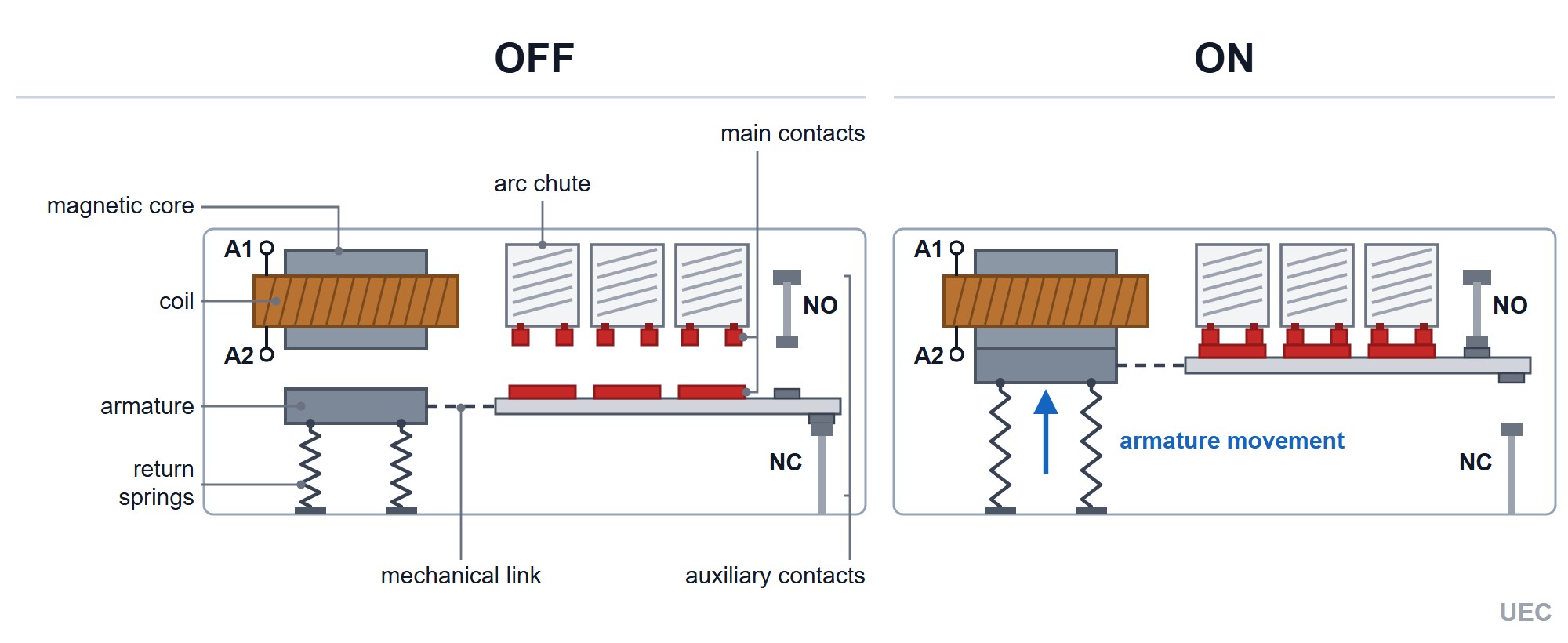
Contactor construction and contact positions in the OFF and ON states
What parts does a contactor consist of?
The main parts are the coil, magnetic core, armature, main contacts, auxiliary contacts, arc chutes and return springs.
The coil together with the fixed magnetic core creates a magnetic field when the voltage Us is applied to it. In the UEC and GEWISS catalog the coil voltage is 230 V AC for the HC and CTR series and 24, 36, 110, 220, 380 or 400 V AC for SB-PC. The armature is the moving part of the magnetic core, on which the moving contacts are mounted, and under the action of the magnetic field it is attracted to the fixed part. The main (power) contacts carry the load current: SB-PC has three of them, HC with two make (NO) contacts has two, and four-contact versions have four. The auxiliary contacts (contact blocks) have a low current rating and work in the control and signaling circuit. The arc chutes extinguish the arc that appears when the contacts open under current, and the return spring returns the armature to its initial position after the voltage is removed.
What is the operating principle of a contactor?
Voltage on the coil creates a magnetic field, which pulls in the armature and closes the main contacts; after the voltage is removed, the springs return the armature to its initial position.
After voltage is applied to the coil, the magnetic field pulls in the armature, the main contacts close, and the auxiliary contacts change state: make contacts close, break contacts open. When the voltage disappears, the magnetic field disappears, the spring returns the armature, and all contacts go back to their initial position. This gives a property that is important for safety: loss of voltage in the control circuit switches the load off. When voltage returns, the load is switched on again only if the "on" command has been retained, for example on a latching switch, which is why motors use a "Start" and "Stop" pushbutton circuit with a self-latching (holding) contact.
How does the power circuit differ from the control circuit?
The power circuit carries the load current through the main contacts, while the control circuit supplies the coil and consists of pushbuttons, relays and auxiliary contacts.
In the power circuit, current flows from the protective device through the main contacts of the contactor to the motor or heater. The control circuit contains a source, pushbuttons, timers, relays and the coil, and its current is lower than the load current. The control circuit voltage does not have to match the load voltage: a 400 V motor can be controlled by a contactor with a 230 V coil if the control circuit is supplied between a phase and neutral. Each circuit has its own protection: the load is protected by a circuit breaker or a fuse sized to the cable cross-section, and the control circuit by a separate low-current circuit breaker or a fuse.
What are the contactor terminal markings?
The coil is designated A1 and A2, the main contacts by the pairs 1/L1-2/T1, 3/L2-4/T2 and 5/L3-6/T3, and the auxiliary contacts by two-digit numbers such as 13-14 and 21-22.
The terminal marking rules are set out in IEC 60947-1 and IEC 60947-4-1, on which DSTU EN IEC 60947-4-1:2019 is based. The main contacts are designated by pairs of single digits: the odd digit is the input and the next even one is the output, that is 1/L1-2/T1, 3/L2-4/T2 and 5/L3-6/T3, and for the fourth pole 7/L4-8/T4. Auxiliary contacts have two-digit numbers, where the last digit shows the function and the first digit is the contact sequence number. The last digits of the numbers define the contact type: 1-2 - break contact (NC, normally closed), 3-4 - make contact (NO, normally open), 5-6 and 7-8 - special-function contacts, for example with a time delay. This rule applies to designations according to the standard, whereas in GEWISS CTR the terminal numbers are positional and do not define the contact function. A thermal relay has a break contact 95-96 and a make contact 97-98. The NO and NC markings next to the digits on the housing only explain the contact type and are not terminals.
| Device | Coil | Main contacts | Auxiliary contacts |
|---|---|---|---|
| UEC SB-PC | A1-A2 as per the diagram in the datasheet | 1/L1-2/T1, 3/L2-4/T2, 5/L3-6/T3 | built-in 13-14 (make) and 21-22 (break): one of the two on 9-32 A, both on 40-95 A |
| UEC SB-AC | - | - | SB-AC-11: 53-54 (make) and 61-62 (break), in other versions as per the attachment datasheet |
| UEC SB-ATD | - | - | on-delay 55-56 and 67-68, off-delay 57-58 and 65-66 |
| UEC HC | A1-A2 | -10: 1-2; -20: 1-2, 3-4; -40: 1-2, 3-4, 5-6, 7-8; -11: R1-R2 and 1-2; -22: R1-R2, 1-2, 3-4, R3-R4 (R is the manufacturer's designation for the break main poles) | no auxiliary contacts |
| GEWISS CTR | A1-A2 | 1-2, 3-4, 5-6, 7-8 | there are no 13-14 designations; the digits are positional: in CTR 1NO+1NC the make contact has terminals 1-2 and the break contact 3-4 (diagram in the GEWISS catalog, p. 37), so the function is not determined from the digits |
What are the NO and NC auxiliary contacts for?
Auxiliary contacts work in the control circuit: the make contact (NO) keeps the coil energized in a self-latching (holding) circuit, and the break contact (NC) provides the interlock.
Auxiliary contacts change state together with the main ones. A make contact (NO, normally open) is open in its initial state and closes when the contactor operates, while a break contact (NC, normally closed) behaves the opposite way. In catalog listings the contact configuration is written as "1 make (NO)" or "1 break (NC)", that is, one make contact or one break contact. An NO contact is used for self-latching and signaling, and an NC contact for electrical interlocking in reversing and ATS circuits. SB-PC rated 9-32 A has only one built-in auxiliary contact, so for circuits that need both NO and NC at the same time, SB-AC auxiliary contacts are added. Among the series considered there are no contactors in which all the contacts are break contacts. In modular contactors, break contacts are found only in the mixed versions UEC HC20-11 (1NO+1NC), HC25-22, HC40-22 and HC63-22 (2NO+2NC) and GEWISS CTR 20 A 1NO+1NC, while in SB-PC the break contact "1 break (NC)" is an auxiliary one.
Contactor types: examples from UEC and GEWISS
By purpose, contactors are divided into modular ones for the panel, power contactors rated 9-630 A, enclosed contactors with a degree of protection of IP54, and reversing ones; the UEC and GEWISS catalog has all four types.
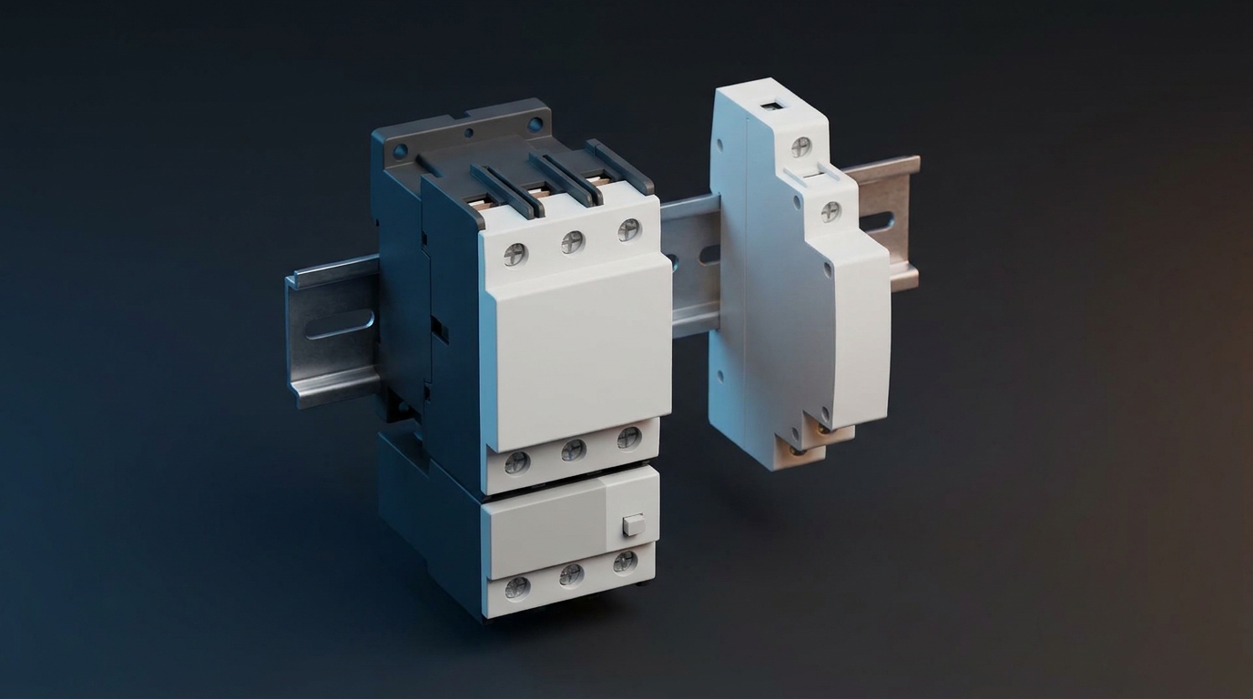
The type of contactor determines not only its size, but also where it is installed, which utilization category it has and what protects the load. Modular devices take one to three modules on a DIN rail and are designed for household and small commercial circuits. Power contactors switch motors, pumps and compressors, and their product pages state the motor power under category AC-3, while for modular UEC HC the product pages state categories AC-1 and AC-7a (for GEWISS CTR the catalog also gives AC-3 and AC-7b up to 30 A). The set of contacts and the coil voltage are also taken from the product page rather than from the ampere figure in the name.
| Series | Current, A | Coil voltage | Contacts | Note from the product page |
|---|---|---|---|---|
| UEC HC | 16, 20, 25, 40, 63 | 230 V AC | 1NO, 2NO or 4NO, 2NO+2NC, in HC20-11 - 1NO+1NC | the product page states AC-1 and AC-7a, the datasheet adds AC-7b, IP20 |
| GEWISS CTR | 20, 25, 40, 63 | 230 V AC (also 220 V DC on 25-63 A) | 1NO, 1NO+1NC, 2NO, 4NO | width of 1, 2 or 3 modules, per the GEWISS catalog AC-1 and AC-7a, AC-3 and AC-7b |
| UEC SB-PC | 9-630 | 24, 36, 110, 220, 380, 400 V AC | auxiliary 1NO or 1NC on 9-32 A, 1NO+1NC on 40-95 A | 3 poles, rated operational voltage 400 V per the product pages, power under AC-3 |
| UEC SB-CMS | 9-40 | 220 V AC (380 V - only on 9-25 A) | auxiliary contacts are not specified on the product page | IP54 enclosure with control buttons per the datasheet, a thermal relay setting range is given |
| UEC SB-PCR | 115-630 | 220 or 380 V AC | auxiliary contacts are not specified on the product page | reversing, 3 poles, power under AC-3 |
Modular contactors UEC HC and GEWISS CTR take one to three modules on a DIN rail, so the place for modular control devices in the panel is reserved already when the panel capacity is calculated. A modular contactor in the panel switches a storage water heater, underfloor heating or a lighting group on a signal from a timer, a thermostat or a relay, and the HC and CTR coils are rated for 230 V AC. The HC product page states categories AC-1 and AC-7a, and there is no category AC-3 in the HC documentation, so direct-on-line starting of larger motors with UEC HC devices is not declared. For motors, power contactors with category AC-3, described below, are used.
UEC SB-PC power contactors rated 9-630 A
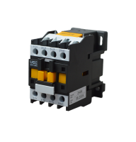
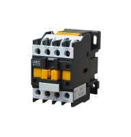
Three-phase SB-PC contactors are available in 19 ratings of 9-630 A with coils for 24, 36, 110, 220, 380 and 400 V AC; these are devices for motors and heavy loads.
All SB-PC have three main contacts and, according to the product pages, a rated operational voltage Ue of 400 V. The rated current is given under category AC-3, so the product page states the motor power at 400 V, and the full range of SB-PC powers under category AC-3 is given in the catalog product pages. At low currents, 9-32 A, the contactor has one built-in auxiliary contact, either a make contact "1 make (NO)" or a break contact "1 break (NC)", and at 40-95 A both are built in, "1 make+1 break (NO+NC)". Coils for 24, 36, 110, 220 and 400 V are found in devices up to 95 A, and from 115 A upward the versions are for 220 and 380 V.
The product page describes the purpose of SB-PC as follows: starting and stopping three-phase squirrel-cage induction motors. According to the same description, these devices switch lighting, heating installations and inductive loads on and off. The SB-PC datasheet permits an ambient air temperature from minus 5 to plus 40 °C and mounting with screws or on a mounting rail on a vertical surface with a deviation from the vertical of up to ±30°. The whole range is listed in the UEC contactor catalog, and the device is briefly presented in the UEC contactor video review.
How does a single-phase contactor differ from a three-phase one?
A single-phase contactor switches phase and neutral with two poles, a three-phase one switches three phases with three poles, and together with the neutral, with four.
The number of poles is determined by the circuit, not by the coil: HC and CTR coils are rated 230 V regardless of the number of poles. In a single-phase circuit both phase and neutral are switched, and switching the neutral conductor alone is not allowed. A three-phase motor needs three main contacts, and a three-phase heater with neutral needs four, with the fourth pole placed in the neutral conductor N after the PEN conductor is split into N and PE, while the PEN conductor itself is not opened. In the catalog, two-contact UEC HC with the -20 designation and GEWISS CTR 2NO are suitable for single-phase circuits, UEC SB-PC has three main contacts, and four-contact HC with the -40 designation and CTR 4NO are suitable for three-phase loads when the neutral is switched together with the phases.
| Circuit | Poles | Catalog example |
|---|---|---|
| Single-phase heater, storage water heater | 2 (phase and neutral) | UEC HC20-20, HC25-20; GEWISS CTR 2NO |
| Three-phase motor | 3 | UEC SB-PC |
| Three-phase heater with neutral | 4 | UEC HC20-40, HC25-40; GEWISS CTR 4NO |
Enclosed SB-CMS contactors with an IP54 degree of protection
SB-CMS is a contactor with a thermal relay and control buttons in an enclosure with an IP54 degree of protection, rated 9-40 A, that is, a ready-made magnetic starter for construction sites and workshops.
According to the description on the product page, the IP54 enclosure makes it possible to use such a contactor on construction sites, in paint-and-varnish, heat-treatment and electroplating workshops, in networks up to 400 V. IP54 means protection against dust and splashes, not explosion protection and not resistance to an aggressive environment: in explosive atmospheres and in rooms with aggressive vapors, equipment in the appropriate design is used, and the permissible environment is confirmed in the datasheet. The datasheet of the series is titled "SB-CMS series contactors (9-95 A) in an enclosure with control buttons", and the photo on the product page shows "I" and "O" buttons; the set of buttons is not specified in the text attributes of the product page. The range consists of versions rated 9, 12, 18, 25, 32 and 40 A with a 220 V coil (380 V - only on 9-25 A). The entry "Ue=220 V" or "Ue=380 V" in the version name means the coil voltage (the SB-CMS datasheet calls it 230 and 400 V), while the operational voltage of the device according to the product page attributes is 400 V. SB-CMS product pages have a thermal relay setting range attribute: 7-10 A for 9 A, 9-13 A for 12 A, 12-18 A for 18 A and 17-25 A for 25 A. All versions are collected in the section on enclosed contactors.
What is a reversing contactor and when is it needed?
A reversing contactor changes the direction of rotation of a three-phase motor by swapping two phases; in the UEC catalog this is SB-PCR rated 115-630 A.
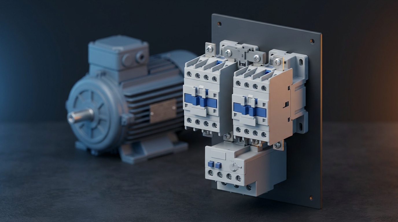
A reversing arrangement consists of two contactors, one of which switches the motor on "forward" and the other, with two phases swapped, "reverse". The rated powers and currents under AC-3 apply when the motor is reversed after it has come to a complete stop; reversing while running and plugging (reverse-current braking) belong to category AC-4, for which the permissible current is much lower (in the SB-PC datasheet, 8.5 A for the 25 A device), so such duties are selected separately according to the manufacturer's documentation. The two devices must not be switched on at the same time, because this leads to a phase-to-phase short circuit, so a reversing assembly always includes an interlock. The SB-PCR range includes 18 versions rated 115, 150, 185, 225, 265, 330, 400, 500 and 630 A with 220 and 380 V coils; the power under AC-3 is 55 kW for 115 A and 335 kW for 630 A. For lower currents, 9-95 A, reversing is built from two ordinary SB-PC contactors and a mechanical interlock, which makes simultaneous closing of both contactors impossible.
Accessories for SB-PC: SB-AC auxiliary contacts, SB-ATD time-delay attachments, mechanical interlock
Auxiliary contacts SB-AC, time-delay attachments SB-ATD and mechanical interlocking are available for SB-PC contactors; all of them are listed in the additional devices section.
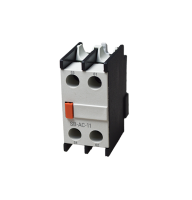
SB-AC auxiliary contacts come in seven versions: 11 (1NO+1NC), 20 (2NO), 04 (4NC), 13 (1NO+3NC), 22 (2NO+2NC), 40 (4NO) and 31 (3NO+1NC), and according to the product pages all of them are compatible with SB-PC. SB-ATD time-delay attachments each have one make and one break contact and two types of delay: on-delay (DT) and off-delay (DR) with ranges of 0.1-3 s, 0.1-30 s and 10-180 s. The mechanical interlock is available in two versions, for SB-PC rated 9-32 A and 40-95 A; it is intended for reversing assemblies. For GEWISS CTR modular contactors there is an additional 1NO+1NC contact half a module wide, which according to the product page signals the position of the contacts. The full list of accessories is in the section on additional devices for UEC contactors.
Contactor or magnetic starter: what is the difference?
A magnetic starter is a contactor combined with a thermal overload relay that protects the motor from overload. The contactor itself only switches the load and leaves the motor without overload protection.
In everyday speech the words "contactor" and "starter" are used interchangeably, but there is a practical difference between them. A contactor is responsible for switching, and a starter for switching together with motor protection, so it is built from a contactor and a thermal relay or from a contactor and a motor protection circuit breaker. The standard DSTU EN IEC 60947-4-1:2019 treats such devices together under the title "Contactors and motor starters".
The selection rule is simple: for a heater, lighting or a master switch a contactor is enough, while for a motor thermal protection is needed as well.
| Parameter | Contactor | Magnetic starter |
|---|---|---|
| Composition | coil, main and auxiliary contacts | contactor plus thermal relay, often in an enclosure, and in SB-CMS also control buttons |
| Motor overload protection | none | yes, it is performed by the thermal relay |
| Short-circuit protection | none, a protective device is needed ahead of it (for SB-PC - gG fuses per the datasheet) | the starter itself does not protect, a protective device is needed ahead of it (for SB-PC - gG fuses per the datasheet); the GEWISS motor protection circuit breaker protects against overcurrents by itself |
| Typical load | heater, lighting, a group of circuits, a motor with separate protection | three-phase motor, pump, compressor, fan |
| UEC and GEWISS example | UEC HC, GEWISS CTR, UEC SB-PC | UEC SB-CMS, SB-PC with SB-TOR; the combination of SB-PC with a GEWISS motor protection circuit breaker is coordinated according to the documentation of both manufacturers |
What is a magnetic starter and what is its purpose?
A magnetic (electromagnetic) starter starts and stops a motor and switches it off in case of prolonged overload. A magnetic starter is built from a contactor, a thermal relay and, depending on the version, an enclosure.
The operating principle of a starter is the same as that of a contactor: the "Start" command applies voltage to the coil, the main contacts close, and the motor receives power. In addition, the thermal relay responds to heating caused by the motor current and, in case of prolonged overload, opens its contact in the coil circuit, after which the contactor switches the motor off. This is how the "start-stop" circuit with a self-latching (holding) contact works. If the voltage disappears, the starter switches off, and the motor does not restart by itself when the voltage returns until there is a new "Start" command.
What types of magnetic starters are there?
Magnetic starters are classified by design, reversing capability, motor protection method and coil voltage.
| Feature | Options | Catalog example |
|---|---|---|
| Version | open, for panel mounting; enclosed (IP54) | SB-PC with SB-TOR; SB-CMS 9-40 A |
| Reversing | non-reversing; reversing | SB-PC; SB-PCR 115-630 A or two SB-PC with an interlock |
| Motor protection | thermal relay; motor protection circuit breaker up to 32 A | SB-TOR; GEWISS motor protection circuit breaker |
| Coil voltage | 24-400 V AC depending on the version | SB-PC: 24, 36, 110, 220, 380, 400 V; SB-CMS: 220 V, also 380 V on 9-25 A |
| Number of poles | three; there are no separate single-phase magnetic starters among the series considered | SB-PC, SB-TOR |
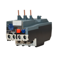
SB-PC contactors and SB-TOR thermal relays each have three poles, so there are no separate single-phase magnetic starters among the series considered. For small motors of household appliances, the UEC HC datasheet declares category AC-7b, and the current and circuit of such a motor are matched against the documentation for the motor itself. For direct-on-line starting of larger motors, devices with category AC-3 are used: SB-PC, SB-CMS or SB-PCR. An open starter is built from SB-PC and SB-TOR, and a ready-made starter in an IP54 enclosure rated 9-40 A is SB-CMS. For motors up to 32 A, thermal protection can be provided by a GEWISS motor protection circuit breaker paired with a contactor.
Which contactor to choose for a typical load?
For a storage water heater and underfloor heating a modular contactor with two make contacts is suitable, for a motor - a power SB-PC or SB-CMS selected by power under AC-3, for load shedding - a modular contactor rated for the current of the non-priority circuit.
The contactor type is determined in this order: first the load and its utilization category, then the design current or the motor power under AC-3, then the number of poles and the coil voltage. For heaters and household loads, modular contactors with categories AC-1 and AC-7a are suitable, and for motors - power contactors with category AC-3 together with a thermal relay. Protection of the circuit is selected separately: for modular contactors - a circuit breaker sized to the cable cross-section, for SB-PC - a gG fuse per the datasheet. Typical matches for household and industrial loads are collected below.
| Load | Contactor type | What to take into account | Catalog example |
|---|---|---|---|
| Storage water heater 1.5-2.5 kW, 230 V | modular with two make contacts | design current 6.5-10.9 A; phase and neutral are switched; per the HC datasheet no more than 100 operations per day | UEC HC20-20, GEWISS CTR 25A 2NO |
| Underfloor heating or an electric boiler 5 kW, 230 V | modular, 25 A | design current 21.7 A; controlled by a thermostat; per the HC datasheet no more than 100 operations per day | UEC HC25-20 |
| Electric boiler 7 kW, 230 V | modular, 40 A | design current 30.4 A; per the HC datasheet no more than 100 operations per day | UEC HC40-20, GEWISS CTR 40A 2NO |
| Three-phase electric boiler 9 kW, 400 V | modular four-contact, 230/400 V | design current 13 A per phase; the fourth contact is placed in the neutral N after the PEN conductor is split; the PEN conductor is not opened | UEC HC20-40, HC25-40 |
| Lighting group | modular | for LED drivers, inrush currents are checked; there are no categories AC-5a and AC-5b in the HC product pages | UEC HC, GEWISS CTR |
| Three-phase motor 4 kW | power or enclosed | thermal protection is needed, setting range 7-10 A in SB-CMS 9 A | UEC SB-PC 9 A with SB-TOR, SB-CMS 9 A |
| Three-phase motor 11 kW | power or enclosed | power under AC-3 from the product page, setting range 17-25 A in SB-CMS 25 A | UEC SB-PC 25 A, SB-CMS 25 A |
| Motor 30-45 kW | power | power under AC-3: 30 kW for 65 A, 45 kW for 95 A | UEC SB-PC 65 A and 95 A |
| Motor reversing | two power contactors with an interlock or a reversing one | mechanical and electrical interlocking are mandatory | UEC SB-PC with an interlock, SB-PCR from 115 A |
| Load shedding | modular, rated for the current of the non-priority circuit | controlled by a load priority relay | GEWISS P COMFORT with UEC HC or GEWISS CTR |
The table should be read as a starting point, not as a ready-made design. The motor power and current from the rating plate take priority over the figures in the rows, and the design current of a heater is always checked against the rated power of the specific appliance. Each row requires its own circuit protection (for SB-PC - a gG fuse per the datasheet), and for motors - also a thermal relay or a motor protection circuit breaker. Before choosing, check all parameters against the product page: in the catalog, the set of contacts, the coil voltage and the utilization category differ even within one series.
Frequently asked questions about contactors and magnetic starters
A contactor switches a load on command but protects neither the circuit nor the motor; what current it can carry depends on the utilization category.
❓ What does a contactor do and what is it used for?
A contactor switches a load on and off on a signal to its coil. It is used to control motors, heaters, lighting and whole groups of circuits from a single switch, timer or relay. A contactor does not protect the circuit against short circuit, so a circuit breaker or a fuse is placed ahead of it. A motor additionally needs a thermal relay or a motor protection circuit breaker.
❓ What types of contactors are there?
By purpose, contactors are divided into modular ones for the panel, power contactors rated 9-630 A, enclosed contactors with an IP54 degree of protection, and reversing ones. Modular UEC HC and GEWISS CTR rated 16-63 A are mounted on a DIN rail for a storage water heater, underfloor heating and lighting. Power UEC SB-PC rated 9-630 A with category AC-3 switch motors, while SB-CMS is a contactor with a thermal relay and control buttons in an IP54 enclosure. Reversing SB-PCR rated 115-630 A change the direction of motor rotation.
❓ What is the difference between a contactor and a magnetic starter?
A magnetic starter is a contactor together with a thermal relay that protects the motor from overload. A contactor only switches, so it is used on heaters, lighting and circuits with separate protection. A ready-made magnetic starter in the UEC catalog is SB-CMS in an IP54 enclosure. For a motor without a ready-made starter, an SB-PC contactor is combined with an SB-TOR relay, and a pair with a GEWISS motor protection circuit breaker is coordinated according to the documentation of both manufacturers, because the SB-PC datasheet requires a gG fuse.
❓ What is a reversing contactor?
It is an assembly of two contactors that changes the direction of motor rotation by swapping two phases. In the UEC catalog this is SB-PCR rated 115-630 A, and for lower currents reversing is built from two SB-PC contactors and a mechanical interlock. The contactors of a reversing assembly have mutual mechanical interlocking (in SB-PCR it is already part of the assembly according to the datasheet, for SB-PC pairs it is fitted separately), while electrical interlocking is made in the control circuit with normally closed (NC) break contacts, which for SB-PCR are added with SB-AC attachments. Without the interlock, simultaneous closing leads to a phase-to-phase short circuit.