
Article Contents
ATS for a Generator and Inverter: Wiring Diagram and Installation


Key takeaways
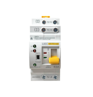
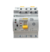
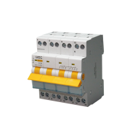
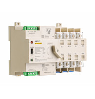
An ATS for a generator and inverter transfers the house load from the grid to the backup source in 50 ms (UEC SB-ATS series) and guarantees that the link between the sources is broken. The transfer switch is installed after the electricity meter and the main circuit breaker, ahead of the group breakers.
Key point: feeding a generator into an ordinary socket is prohibited — it creates backfeed into the external line. In a "grid ↔ battery" scheme a hybrid inverter usually needs no external ATS, but as soon as a generator enters the system, a dedicated transfer switch is required.
Hello! This material was prepared by the UEC engineering department. We manufacture the SB-ATS series of automatic transfer switches and specify backup power panels every day, so we show the diagrams the way a qualified electrician actually builds them, not as a simplified picture.
This article is about the wiring diagram: where to run the line, neutral and earth, where the ATS sits in the panel, and how the hybrid-inverter scenario differs from the generator one. Rating calculation by power and the interlocking principle are only mentioned briefly here — they are covered in detail in the complete ATS guide.

⚠ WARNING! Working with electrical equipment is life-threatening!
Connecting an ATS and a backup power supply (especially a generator input) involves the risk of backfeed and requires a qualification of at least electrical safety group III. Have the installation carried out by a licensed electrician.
Why a generator and an inverter need an ATS
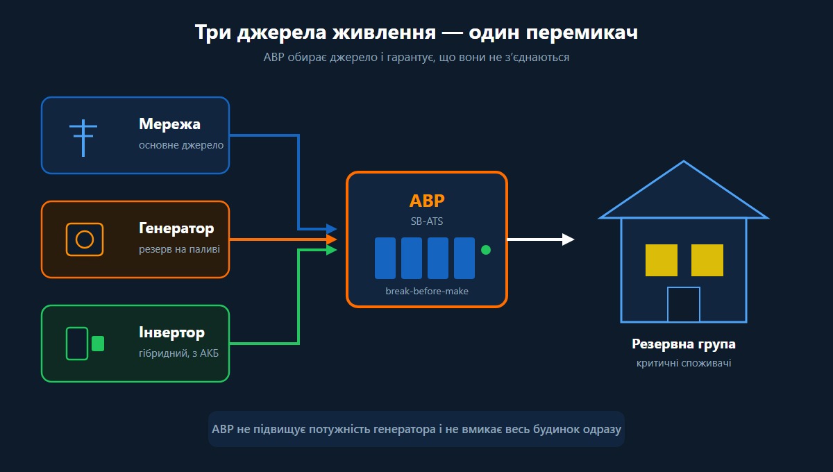
An ATS is needed so that the backup source picks up the load automatically and so that the grid and the generator are never connected to each other. Without a transfer switch, any backup power supply becomes either a manual operation or a source of accidents.
Requires a transfer device
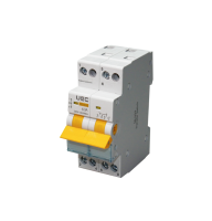
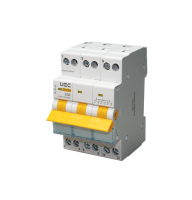
A generator supplies the house only when the grid is gone, so a device is needed to disconnect the grid and connect the generator. If a person does this, a manual 1-0-2 changeover isolator is used. If the transfer must happen without the owner present, an automatic transfer switch is installed: it monitors the presence of voltage itself and moves the load within tens of milliseconds.
Often has its own logic
An inverter (especially a hybrid one) often has its own transfer logic, so it does not always need an external ATS — there is a separate section on this below. What an ATS does NOT do: it does not increase the generator's power, it does not switch on the whole house at once, and it does not start the generator engine by itself without the corresponding auto-start logic.
How an ATS works with a generator: the overall logic
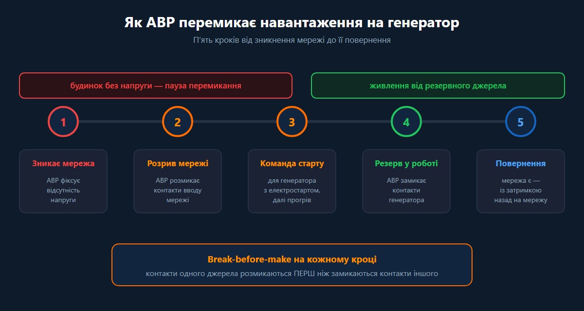
The ATS constantly monitors the voltage of the main source and, as soon as the grid disappears, transfers the load to the backup after a short delay; when the grid returns, it moves the load back. The transfer follows the break-before-make principle: the contacts of one source open BEFORE the contacts of the other close, so the two sources are never connected at the same time [4].
The operating logic in automatic mode consists of several steps:
- The grid disappears — the ATS registers the absence of voltage.
- The ATS disconnects the grid input (opens the contacts).
- A command is issued to the backup source; for a generator with electric start this is the engine start command, after warm-up (typically 5-10 minutes for the manual scenario) [4].
- The ATS closes the generator contacts — the load is supplied from the backup source.
- The grid returns — after a return delay the ATS opens the generator and switches the grid back on.
An important limitation:
for fully automatic engine starting, the generator must have an electric start. The UEC SB-ATS series performs load switching itself (automatically or manually) — the engine auto-start function is provided by separate generator auto-start logic, so these two units are selected together [7].
The ATS wiring diagram for a generator (grid-generator)
The basic diagram has three groups of terminals: the grid input, the generator input and the output to the load (the consumer panel). The ATS switches the line and neutral of both sources onto a common output, while the protective conductor PE runs straight through and is not switched.
The conductor sequence in principle:
- The line L of the grid goes to the grid input terminal of the ATS; the line L of the generator goes to the generator input terminal; the outgoing line goes to the load panel.
- The neutral N of a multi-pole transfer switch is switched together with the lines — to isolate the house from the second source completely and avoid creating a parallel link between the neutrals [3].
- The PE (earth) is not broken by the transfer switch: the generator frame must be bonded to the building's earthing system, and the load's PE remains continuous [3].
Below is a clean vector diagram of a single-phase grid-generator input through an ATS. The exact switching of neutral and earth depends on the site's earthing arrangement (TN-C-S, TN-S) and is agreed with the electrician.
For a three-phase supply the logic is the same, but three lines L1/L2/L3 are switched together with the neutral (4P), and the PE likewise stays continuous.
Where to place the ATS in the panel: order of devices
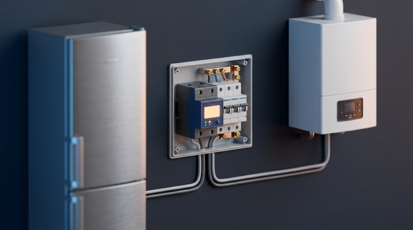
The ATS is installed after the electricity meter and the main circuit breaker of the grid, but before the consumer group breakers — so that it only governs the choice of source, while protection and metering stay in their places [2]. This is a requirement of the State Energy Supervision authority and a key safety condition: the source transfer switch must not be installed ahead of the meter.
The typical sequence in the panel from the supply to the consumer:
| Position | Device | Purpose |
|---|---|---|
| 1 | Grid input | Cable from the utility meter |
| 2 | Main circuit breaker | Protection and manual disconnection of the grid |
| 3 | ATS (SB-ATS) | Source selection: grid or generator |
| 4 | Generator input | Separate cable from the generator (via its own breaker) |
| 5 | Voltage relay (if required) | Protection against over/undervoltage of the backup source |
| 6 | Group breakers / RCD | Distribution to the backup group of consumers |
The meter comes before the ATS — backup power is also metered or, depending on the utility's scheme, the generator branch is taken out separately; this is agreed with the distribution system operator. A voltage relay is often installed next to the ATS, because the voltage from a domestic generator can be unstable, and both devices work together in the panel.
Does an inverter need an external ATS, or is the built-in bypass enough?
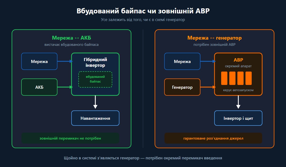
If the task is only to switch between the grid and the battery, a hybrid inverter is usually served by its built-in bypass (transfer relay): it takes the load onto the battery itself within a few milliseconds when the grid fails [5]. An external ATS becomes necessary when a generator is added to the scheme as a separate source.
Let us look at the two scenarios separately, because this is exactly where most online advice gets confused.
When is the inverter's built-in bypass enough?
The built-in bypass is enough in a grid ↔ battery scheme, where the backup source is only the battery. In grid mode a hybrid inverter supplies the load directly from the grid and, when the grid fails, switches to battery power through the inverter almost without a pause — no external transfer switch is needed for this [5]. This is the classic home UPS/hybrid setup without a generator.
When does an inverter need an external ATS?
An external ATS is required in a grid ↔ generator ↔ inverter scheme, when you need to choose automatically between the grid and the generator, control the generator auto-start and guarantee separation of the sources [5]. A dedicated transfer switch is also installed when the inverter has no generator input, or when the generator is to supply the house as an independent backup source rather than merely charge the battery.
Where should the generator's AC input be connected on a hybrid inverter?
The generator is connected to the input the manufacturer intended: to a dedicated GEN port if there is one, or to the common AC-in (grid-in) — but only if the manual permits it and the generator's parameters are compatible [5]. On models with a separate GEN port, that is where the priority and charge current settings are available; that is why the generator-to-inverter wiring is checked against the specific model's datasheet rather than built from a generic picture.
A brief comparison of the two solutions:
| Criterion | Inverter's built-in bypass | External ATS |
|---|---|---|
| Sources | Grid ↔ battery | Grid ↔ generator (↔ inverter) |
| Transfer | Internal, milliseconds | External, tens of milliseconds |
| Generator control | None | Yes, with auto-start |
| Separation of sources | Within the inverter | Guaranteed, a dedicated device |
| When to choose it | Battery-only backup | A generator is part of the scheme |
Why you must not feed a generator into a socket
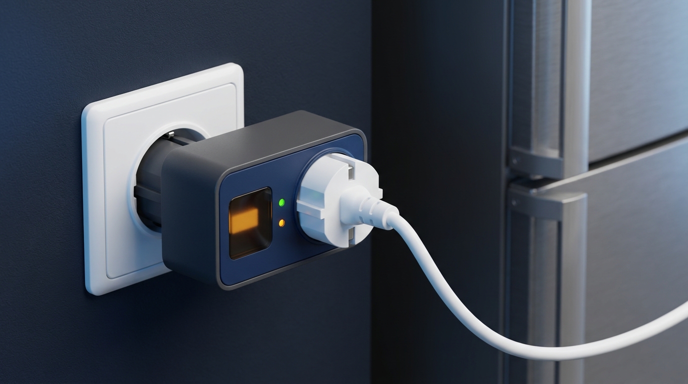
Connecting a generator into an ordinary socket in the building without a transfer switch is prohibited, because it creates backfeed — the generator sends voltage back into the external line, which an emergency crew may believe to be de-energised [2][5]. This is a lethal hazard for line workers and a risk of short circuit and fire.
Approximate socket ratings according to the State Energy Supervision authority: a 10 A socket withstands about 2.2 kW, a 15 A one about 3.5 kW [2]. A powerful generator must not be fed through such a socket even temporarily — the current will exceed the value the socket is rated for. There is only one correct route: the generator input goes through a transfer switch (an ATS or a manual 1-0-2 changeover isolator) with interlocking against simultaneous connection of the sources, installed after the meter and the main breaker [2].
Do not confuse an ordinary domestic socket with a generator inlet (an input connector). An inlet is a dedicated fixed input connector on the wall of the house, through which the cable from the generator enters the panel and is necessarily switched by a transfer switch (a 1-0-2 changeover isolator or an ATS) with interlocking. The inlet does not replace the transfer switch, it merely provides a safe place to connect the cable; the prohibition concerns precisely feeding a generator into an ordinary domestic socket without a transfer switch.
What must NOT be present in the scheme (YMYL safety checklist):
- There is no direct connection between the generator and a socket in the house.
- There is no possibility of closing the grid and the generator at the same time (break-before-make interlocking is mandatory).
- There is no switching of the PEN conductor as a working conductor — it is not broken.
- There is no generator input ahead of the meter and the main breaker.
How to choose the ATS pole configuration: 2P or 4P?
The pole configuration is chosen according to the supply scheme: for a single-phase 230 V grid you take 2P (line L and neutral N are switched), for a three-phase 400 V grid — 4P (three lines L1/L2/L3 plus neutral N) [3]. The neutral is broken synchronously with the lines, in order to isolate the house from the second source completely.
Mapping to the UEC SB-ATS line:
| Model | Poles | Current | For which grid |
|---|---|---|---|
| SB-ATS-2-063 | 2P | 63 A | Single-phase 230 V |
| SB-ATS-4-063 | 4P | 63 A | Three-phase 400 V |
| SB-ATS-4-100 | 4P | 100 A | Three-phase 400 V, higher load |
The rating of the transfer switch must equal or exceed that of the main circuit breaker and the calculated load of the backup group, with a current margin [6]. We do not repeat the detailed rating calculation by the power formula or the 10-30% margin principle here — they are covered step by step in the complete ATS guide. What matters here is something else: only the critical group of consumers should be backed up (heating boiler, circulation pump, refrigerator, lighting), because a generator is usually weaker than the grid and will not carry the whole house [6].
What to do if the generator and the grid have different phase configurations
A common case: the grid supply is three-phase (400 V) while the generator is single-phase (230 V). A universal "just use 4P" is not enough here. If a three-phase house is backed up by a single-phase generator, only the critical single-phase group is supplied from the backup source: it is separated out and routed through a transfer switch of the corresponding pole configuration, while the remaining phases are left without backup. A three-phase generator feeding a single-phase load is connected with one phase, distributing the power evenly across the windings so as not to overload one of them. The number of poles of the transfer switch is chosen according to the actual scheme of both sources, not the "theoretical" supply; matching the phases and neutral with different phase configurations is a designer's task, because a mistake creates imbalance and dangerous operating modes.
How to earth the generator and what to do with the neutral
The generator frame must be bonded to the building's PE system, and when the generator is connected, the neutral is broken synchronously with the lines by a multi-pole transfer switch [3]. The exact neutral and earth arrangement depends on the site's earthing system (TN-C-S, TN-S) and on the generator type, so it is settled by the electrician according to the equipment datasheet.
⚠ An honest limitation: there is no universal answer of "always 4P and always break the neutral" — in a TN-C-S arrangement the generator may be a separately earthed source, and then the switching of the neutral depends on how the neutral and the protective conductor are connected on site [3]. A PEN conductor is not switched as a working conductor. This is exactly why the generator input is the case where the scheme must be agreed with a qualified electrician rather than assembled from a generic picture found online.
If you are still choosing between automatic and manual transfer for a generator, the comparison of scenarios and costs is covered in the article ATS or manual transfer switch; and how to build a manual generator input specifically is covered in the article on the 1-0-2 changeover isolator. Typical operating and maintenance mistakes with an ATS are collected separately in the material on common ATS mistakes.
Questions and answers (FAQ)
❓ Can a generator be plugged into a socket in the house?
No. This creates backfeed into the external line and poses a lethal hazard to emergency crews. A generator is brought in only through a transfer switch (an ATS or a 1-0-2 changeover isolator) with interlocking, installed after the meter and the main breaker [2].
❓ Does the generator need to be earthed?
Yes, the generator frame must be bonded to the building's PE earthing system. The exact neutral and earth arrangement depends on the site's earthing system and is agreed with the electrician [3].
❓ Should you choose 2P or 4P for an ATS?
2P — for a single-phase 230 V grid (line + neutral), 4P — for a three-phase 400 V grid (three lines + neutral). The neutral is broken together with the lines [3].
❓ Does an inverter's built-in bypass replace an external ATS?
In a grid ↔ battery scheme the built-in bypass is enough. An external ATS is needed when the system includes a generator as a separate source with auto-start and guaranteed separation of grid and generator is required [5].
❓ Why does the generator breaker trip after transferring to the backup source?
Most often this is an overload: more consumers are connected to the backup group than the generator can carry, or powerful loads with a high inrush current start simultaneously. Only the critical group should be backed up, matched to the generator's real output [6].