Article Contents
RCD Wiring Diagram in a Panel: Single-Phase and Three-Phase


Key takeaways
Over 80% of residential electrical panels in Ukraine are assembled with a single-phase layout, where the RCD is the only barrier between current leakage and a person being shocked. Below are three working wiring diagrams for a residual current device (RCD), conductor cross-sections and five mistakes that cause nuisance tripping.
Key point: the RCD is installed after the input breaker and before the group breakers; the protective PE conductor never passes through the device.

Hi, I am an engineer at the UEC technical department. Every day we advise electricians and designers on the correct assembly of panels with residual current devices.
In this article you will find three proven RCD wiring diagrams (single-phase, combined and three-phase), a conductor cross-section table and a breakdown of five installation mistakes that make the device fail to trip or trip for no reason.

⚠ Warning! Working with electrical equipment is life-threatening!
Work on an electrical panel requires a qualification of at least group III in electrical safety. Entrust the installation to a licensed electrician. Perform all work with the power disconnected and after verifying the absence of voltage with a measuring device.
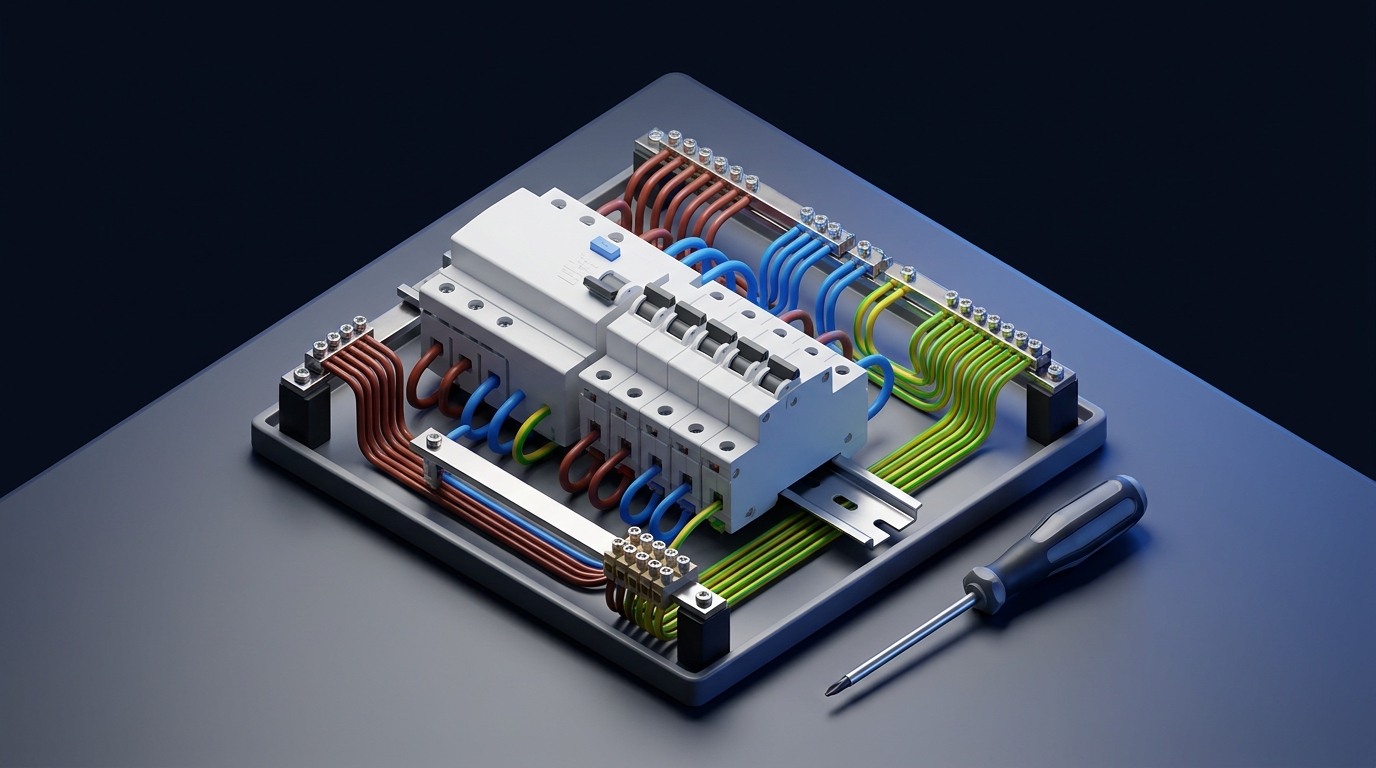
Where the RCD is installed in the panel: sequence
The RCD is always installed after the input circuit breaker and before the group breakers. A typical sequence of components in the panel [1]:
- Input breaker (2P, 32–40 A) — protects the line against overload and short circuit.
- Meter (if located in the panel).
- Voltage relay (if present) — protection against overvoltage and voltage sag.
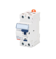
- RCD (2P or 4P, 30 mA) — protection against current leakage.
- Group breakers (1P, 10–25 A) — protection of individual lines.
The rated current of the device must be one step higher than the input breaker: input 32 A → RCD 40 A. The device has no thermal release, so it needs overload protection [2].
Important for safety:
The protective PE conductor is not connected to the residual current device — it runs on a separate busbar directly to the loads.
| Panel component | Rating | Conductor cross-section |
|---|---|---|
| Input breaker → RCD | 32–40 A | 6 mm² (Cu) |
| RCD → group breakers | 30 mA / 40 A | 6 mm² (Cu) |
| Socket group | 16–20 A | 2.5 mm² (Cu) |
| Lighting group | 10 A | 1.5 mm² (Cu) |
| Power line (boiler, cooker) | 25–32 A | 4–6 mm² (Cu) |
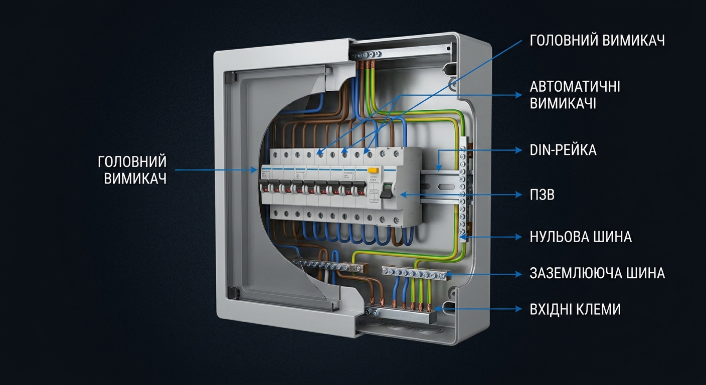
Diagram 1 — single-phase RCD connection
The most common diagram for apartments and small houses with a single-phase 220 V supply.
What we connect:
- RCD input (upper terminals): phase conductor L — from the output of the input breaker; neutral N — from the neutral busbar after the meter.
- RCD output (lower terminals): L — to the busbar of the group breakers; N — to a separate neutral busbar that supplies only the groups protected by this RCD.
The group breakers are connected to the phase output of the RCD via a busbar comb. The neutral conductors from each group return to "their own" neutral busbar — the one from the RCD output [1][2].
The cross-sections for the single-phase diagram are given in the table above.
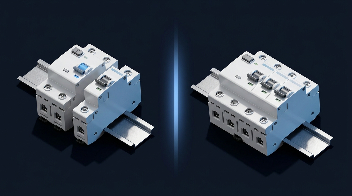
Diagram 2 — RCD + RCBO on group lines
A general residual current device at the input is supplemented with RCBOs on critical lines: bathroom, washing machine, boiler. This provides selectivity — in case of leakage a single line is switched off, not the whole panel [3].
Order:
- Input breaker → general RCD (fire-protection, 100–300 mA) → group lines.
- On critical groups — an RCBO (30 mA), for example the SB-R10N from UEC.
- On the remaining groups — ordinary breakers protected by the general RCD.
This diagram makes sense when there are "wet" lines (bathroom, washer, dishwasher) and uninterrupted operation is required. For more detail — on how to correctly connect an RCBO.
Diagram 3 — three-phase connection
For private houses with a three-phase 380 V supply, a four-pole RCD (4P) is used. The principle is the same, but three phases (L1, L2, L3) and the neutral (N) pass through the device [2].
Sequence:
- Input breaker 3P (25–40 A) → RCD 4P (40–63 A / 30 mA).
- From the RCD output, the three phases are distributed to the group breakers: L1 — group 1 (kitchen), L2 — group 2 (sockets), L3 — group 3 (power loads).
- The neutral conductor from the RCD output goes to a separate neutral busbar for the protected groups.
Cross-sections: the supply and the section up to the RCD — 10 mm² (Cu), from the RCD to the group breakers — 6 mm², single-phase groups — 2.5 mm².
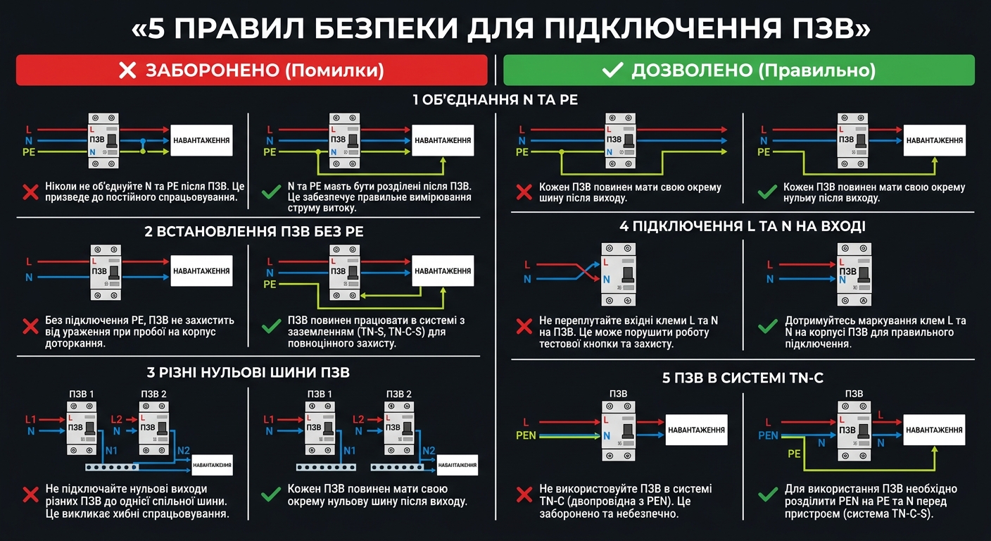
RCD connection mistakes
Five mistakes that make the RCD fail to trip or trip for no reason [1][3]:
❌ 1. Mixed neutrals of different groups
Neutrals from groups of different devices end up on the same busbar — part of the return current "flows" bypassing the transformer, and both devices trip falsely.
Rule: each device must have its own neutral busbar.
❌ 2. Reversed polarity (L and N swapped)
If you connect L and N the wrong way round, the test button will not work, and the protection may fail to trip on leakage.
Rule: follow the markings on the housing. After installation, press "Test" — the device must switch off.
❌ 3. No upstream breaker before the RCD
Without a breaker in front of it, the RCD contacts will weld together on a short circuit.
Rule: before each RCD — a breaker with a rating that does not exceed the RCD rating.
❌ 4. Load connected to the input (top)
The supply is fed from the bottom, the load from the top. The direction of current through the transformer is reversed.
Rule: the supply always goes to the upper terminals (IN), the load to the lower ones (OUT).
❌ 5. PE conductor routed through the RCD
The PE is passed through the residual current device together with L and N — a constant "leakage" and immediate tripping.
Rule: the PE conductor runs on a separate busbar and never passes through the RCD.
FAQ — RCD connection
❓ Can one RCD be used for the whole panel?
Yes, but on leakage in any line the whole house will be de-energized. For selectivity it is better to combine a general fire-protection RCD (100–300 mA) with RCBOs (30 mA) on critical groups — diagram 2 above.
❓ Which RCD sensitivity to choose: 10 mA or 30 mA?
For protecting people (bathroom, sockets) — 30 mA. A 10 mA RCD makes sense only for a dedicated bathroom line. At the input for fire protection — 100–300 mA [2].
❓ Does an RCD work without earthing?
Yes, but with earthing (TN-S or TN-C-S) the RCD reacts faster: a leakage to the housing immediately creates an imbalance, and the device switches off the line before contact with a person [1][2].
❓ What to do if the device keeps tripping?
Check: (1) whether the neutrals of different groups are joined, (2) whether there is insulation damage, (3) whether the PE is routed onto the neutral busbar. Disconnect the groups one by one — you will find the faulty line.
❓ How does an RCD differ from an RCBO?
An RCD reacts only to current leakage and needs a separate breaker in front of it. An RCBO = RCD + circuit breaker in one housing. To choose between them — see the article RCD or RCBO — which to choose.