Article Contents
Voltage Relay Wiring Diagram for Electrical Panel: Single-Phase and Three-Phase


Key takeaways
A voltage relay disconnects the circuit in 0.02 seconds during a voltage surge — but only if it is wired correctly. Below you will find 5 field-tested wiring diagrams and 6 mistakes we see even from experienced electricians.
Key rule: the correct sequence in the panel is meter → main breaker → voltage relay → RCD → group breakers. The relay always goes BEFORE the RCD.
Hello, I'm Oleg, an electrical engineer at UEC with 12 years of experience designing electrical panels for residential and industrial projects.
In this article we will review 5 proven voltage relay wiring diagrams — from a basic single-phase setup to a three-phase installation with a contactor, along with common installation mistakes.

Warning! Working with electrical equipment is life-threatening!
All work in the electrical panel must be performed only by qualified electricians with the power disconnected. Before starting work, be sure to de-energize the line and verify the absence of voltage with a measuring device.
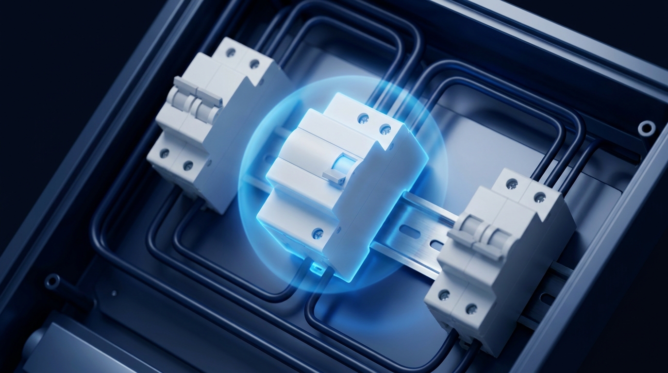
Where is a voltage relay installed in the panel?
A voltage relay is a modular protection device mounted on a DIN rail inside an electrical panel (distribution board). Its position in the circuit is clearly defined [1]:
Sequence in the panel:
meter → main breaker → voltage relay → RCD → group breakers
The main circuit breaker is installed BEFORE the relay and limits the maximum current. The RCD (residual current device) is mounted AFTER the relay because a voltage surge can damage the RCD's electronics. An RCBO combines the functions of a breaker and RCD and is placed on group circuits [2]. The rated current of the relay must be no less than the rating of the main breaker.
5 voltage relay wiring diagrams
Diagram 1 — single-phase relay in the panel (basic)
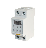
The simplest option for an apartment. The phase wire from the output of the main breaker connects to the In terminal of the relay. From the Out terminal it goes to the phase busbar of group breakers. The neutral wire (N) runs directly to the neutral bus, and the relay's N terminal also connects to the bus [1].
Cable cross-section: 4–6 mm² copper for the supply line, 2.5 mm² for the busbar. Thresholds per EN 50160: upper 245–250 V, lower 180–190 V, delay 5–10 s.
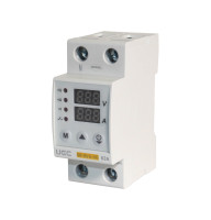
Diagram 2 — single-phase + contactor (>40 A)
For loads exceeding 40 A, the relay controls a contactor rather than breaking the power line directly. The power phase passes through the contactor (terminals L1→T1), and the relay output energizes the contactor coil (A1/A2, 220 V). A 2 A breaker protects the coil [2]. Power cables: 10–16 mm², coil: 1.5 mm².
Diagram 3 — socket relay
A socket relay (adapter) plugs into a standard 220 V outlet and protects a single appliance — up to 16 A (3.5 kW). Thresholds: upper 250 V, lower 180 V, delay 5–300 s. Suitable for a refrigerator or boiler without modifying the panel [3].
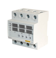
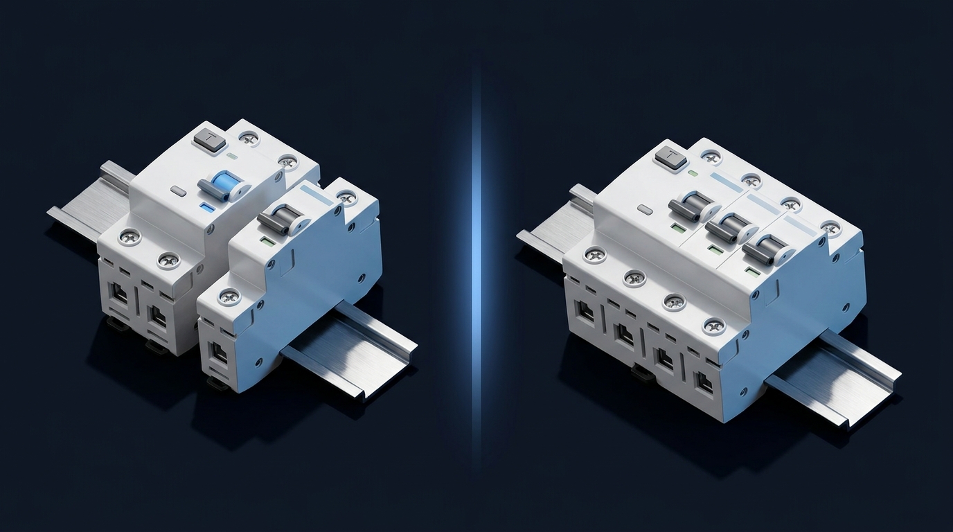
Diagram 4 — three-phase relay
For a private house with a three-phase supply but no three-phase equipment — use 3 separate single-phase relays, one per phase (L1, L2, L3). This ensures selectivity: only the affected phase disconnects [2]. If three-phase equipment is present — use one three-phase relay (ZUBR 3F) plus single-phase relays on individual circuits. Cable cross-section: 6–10 mm² copper per phase.
Diagram 5 — relay + RCD/RCBO
Full protection circuit: meter → main breaker → voltage relay → RCD → RCBOs or group breakers. The neutral from the relay goes to the bus, then to the RCD input. The relay is placed specifically BEFORE the RCD to protect its electronics from overvoltage [1][3].
6 installation mistakes even electricians make
| # | Mistake | Consequences | How to fix |
|---|---|---|---|
| 1 | Incorrect neutral wiring — N and L terminals swapped | Relay does not detect voltage, appliances burn out | Phase to L-in, neutral to N-in. Verify with a multimeter |
| 2 | Relay installed AFTER the RCD | RCD unprotected from overvoltage, false trips | Sequence: meter → breaker → RELAY → RCD → breakers |
| 3 | 16 A relay on a 40 A load | Contact overheating, fire risk | Relay rating ≥ main breaker rating |
| 4 | Load >40 A without a contactor | Overheating, arcing at relay contacts | Add a contactor with appropriate rating |
| 5 | Missing PE grounding | Voltage potential on appliance housings | TN-C-S or TT system with a PE conductor |
| 6 | Unstable DIN rail | Vibration, false trips | 35 mm DIN rail, rigid mounting to the panel |
FAQ — voltage relay wiring
❓ Should the relay go before or after the breaker?
AFTER the main circuit breaker and meter. Installing it before the meter is prohibited by electrical regulations — the meter must record all consumption, and the relay must be protected by the breaker against short circuits [1].
❓ How do I wire a voltage relay in the panel correctly?
Phase from the main breaker output goes to the In terminal. From the Out terminal it connects to the group breaker busbar. Neutral goes to the neutral bus and the relay's N terminal. Cable cross-section: at least 4 mm² copper. Thresholds: upper 245–250 V, lower 180–190 V [1][3].
❓ Is a contactor needed for a 63 A relay?
If the actual load does not exceed 63 A and the relay is rated for that current — no contactor is needed. A contactor is mandatory when the load exceeds the relay's rating (typically 40 A and above) [2].