
Circuit Breakers: Schematic Symbols, Markings, and Key Parameters
A circuit breaker is a protective device that automatically opens an electrical circuit in case of overload or short circuit. Its main function is to protect wiring, equipment, and people from abnormal operating conditions in the network. Depending on the type, breakers can be used in residential, commercial, and industrial installations.
Today, you can buy circuit breakers in any specialized store, but to make the right choice, it's important to understand the technical specifications, markings, and schematic symbols.
What Is a Circuit Breaker?
The primary purpose of a circuit breaker is to prevent short circuits and overloads. Manufacturers also note in technical documentation that the device trips when the permissible load is exceeded. However, to precisely monitor the load and avoid cable overheating, it's better to use dedicated devices designed for such tasks.
The operating principle of circuit breakers is based on the type of built-in trip unit—thermal or electromagnetic. Most modern models combine both (hybrid devices):
-
Thermal trip unit reacts to increased current by heating a bimetallic strip. Once sufficiently deformed, the strip mechanically breaks the circuit. After cooling, the breaker can be reused. This system is not instantaneous—it requires time to heat up.
-
Electromagnetic trip unit provides instant disconnection. When a current spike occurs, the coil generates a magnetic field that shifts the core, breaking the contact immediately. This mechanism is considered high-speed.
Thanks to this combination, circuit breakers can effectively respond to both short-term current spikes (short circuits) and prolonged overloads.
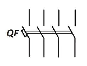
Circuit Breaker Symbols in Schematics
According to DSTU IEC 60617, a circuit breaker is represented by the symbol “⎯o⎯” (simplified) or “⎯⎯[ ]⎯⎯” (full graphical symbol), where the brackets indicate the protective mechanism.
On a schematic, the circuit breaker consists of:
-
A rectangle — represents the device body;
-
A diagonal line — shows contact disconnection during tripping;
-
Contacts — two or more connected to the diagonal line, indicating circuit breakage in various points;
-
Additional marks — indicate the breaker type (current type, tripping time, etc.).
In residential switchboards, circuit breakers are labeled as “QF1,” “QF2,” etc., where “QF” denotes a switching device, and the number is sequential.
Examples of Graphic Symbols:
-
(a) Single-pole
-
(b) Double-pole
-
(c) Triple-pole
-
(d) Four-pole


Circuit Breaker Markings
Each breaker has markings on the front panel with its key technical characteristics.
Example: C16 230/400V 6kA
Decoding the marking:
-
C16 – “C” indicates tripping characteristics; “16” is the rated current (A);
-
230/400V – working voltage (single-phase/three-phase);
-
6kA – breaking capacity: the maximum short-circuit current the breaker can interrupt without damage.
Key Parameters of Circuit Breakers
Rated Current (In)
Specifies the maximum continuous current the breaker can handle without tripping. Typical values: 6, 10, 16, 20, 25, 32 A. The breaker should match the cable cross-section and expected load. For example, for 9A current, a 10A breaker is suitable.
-
25–32 A – input lines
-
16–20 A – power outlets
-
6–10 A – lighting
-
Accurate load calculation is recommended. Incorrect ratings may cause frequent tripping or lack of protection.
Tripping Curve (Type B, C, D)
Indicates how fast the breaker trips during a short circuit:
-
B – fast response, low fault current threshold; ideal for stable loads like lighting.
-
C – universal, common in residential and office networks.
-
D – delayed tripping, suitable for equipment with high inrush current (motors, compressors).
Number of Poles (1P, 2P, 3P, 4P)
Indicates how many conductors are protected:
-
1P/2P – single-phase (L or L+N)
-
3P/4P – three-phase (3L or 3L+N)
Though larger breakers take up more space, they offer better safety by disconnecting both phase and neutral.
Nominal Voltage (V)
Choose 230V for single-phase AC, 380V for three-phase. DC breakers exist for control systems or industrial power installations with 24–880V range.
Breaking Capacity (kA)
The highest fault current the breaker can interrupt:
-
4.5–6 kA – suitable for household use
-
10 kA and higher – industrial networks
Higher-rated breakers often use silver contacts to ensure durability.
Number of Modules
Depends on DIN rail space:
-
Single-phase: 1–2 modules
-
Three-phase: 3–4 modules
-
Compact models: 0.5 modules (for add-on contacts)
Avoid using overrated breakers as they may fail to protect against overloads, causing overheating or fire.
Recommendations for Choosing Circuit Breakers
For Apartments:
-
Type: B or C
-
Current: 16–25 A
-
Poles: 1P or 2P
For Private Homes:
-
Separate breakers for each line (lighting, sockets, boiler)
-
Proper breaking capacity is essential
For Offices or Shops:
-
Consider power reserve
-
Use C or D type for devices with high starting current (e.g., air conditioners)
A reliable circuit breaker means protection for both your equipment and the entire electrical system.
Conclusion
Circuit breakers are a vital component in any electrical system. Choosing the right one—understanding its markings, parameters, and schematic representation—ensures safe and stable network performance. It also helps avoid connection errors and optimize installation and operating costs.

